
Range, Span, LRV & URV – Complete Guide for Instrument Technicians
1. Introduction
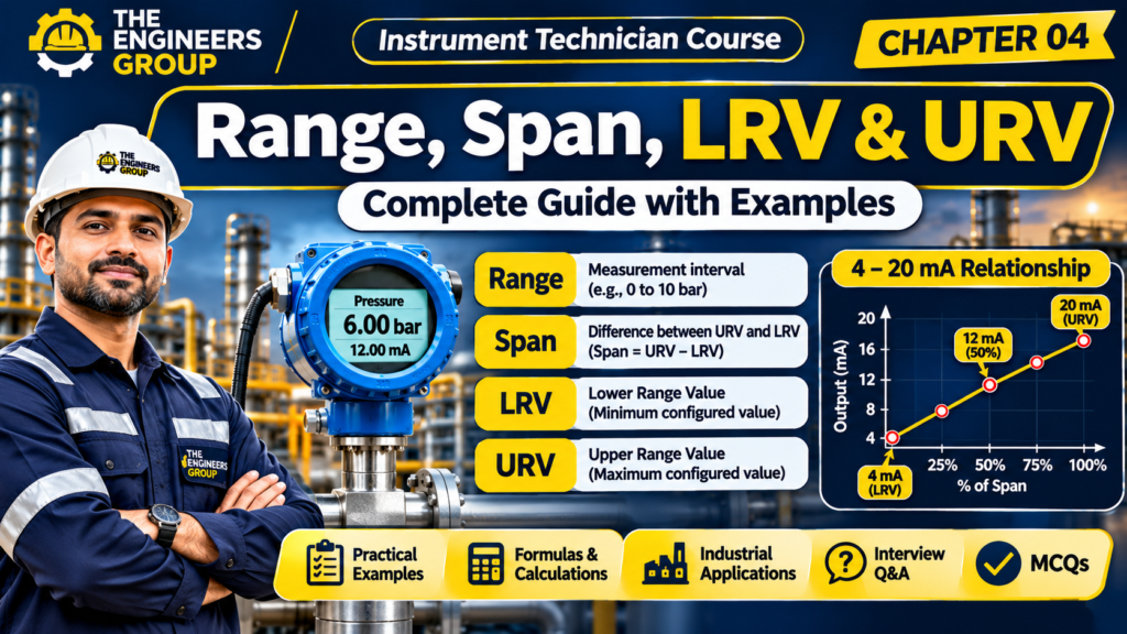
In industrial instrumentation, every measuring instrument is designed to measure a specific range of process variables such as pressure, temperature, flow and level.
For example, a pressure transmitter may be configured to measure pressure from 0 to 10 bar and generate a standard 4–20 mA output signal.
To understand how an instrument measures and converts process values into electrical signals, Instrument Technicians must understand four important terms:
- Range
- Span
- LRV (Lower Range Value)
- URV (Upper Range Value)
These terms are commonly used during instrument selection, configuration, calibration, commissioning and troubleshooting.
In this chapter, we will understand each concept with practical industrial examples.
2. What is Instrument Range?
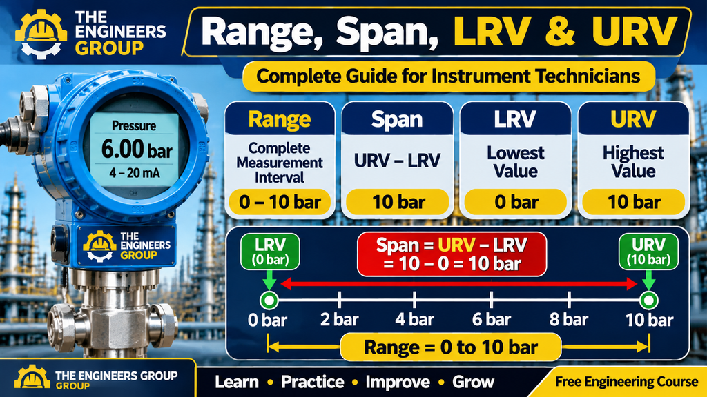
Range is the set of values between the lower and upper limits within which an instrument is configured or specified to measure a process variable.
In simple words, range tells us the minimum and maximum values an instrument is intended to measure.
Example:
A pressure transmitter has the following measuring range:
- Lower Limit = 0 bar
- Upper Limit = 10 bar
Therefore:
Instrument Range = 0 to 10 bar.
This means the transmitter is configured to measure pressure between 0 bar and 10 bar.
Other Industrial Examples:
| Instrument | Measuring Range |
|---|---|
| Pressure Transmitter | 0–10 bar |
| Temperature Transmitter | 0–200°C |
| Flow Transmitter | 0–100 m³/h |
| Level Transmitter | 0–5 metres |
| Differential Pressure Transmitter | 0–100 kPa |
MASTER INDUSTRIAL
INSTRUMENTATION
Build your technical knowledge with our Instrument Technician E-book – English Edition.
Instrument Technician E-book (English Edition)
Learn essential industrial instrumentation concepts, measurement systems, calibration and troubleshooting in one practical guide.
WHAT YOU WILL LEARN:
- Fundamentals of Industrial Instrumentation
- Pressure, Temperature, Flow and Level Measurement
- Sensors, Transmitters and Control Valves
- Instrument Calibration and Troubleshooting
- PLC, SCADA and Industrial Control Systems
- Essential Instrumentation Interview Preparation
SPECIAL OFFER PRICE
Digital eBook – English Edition
Secure online payment • Digital delivery via email
No physical book will be delivered.
Ideal For:
ITI & Diploma Students | B.Tech Graduates | Instrument Technicians | Junior Engineers
Learn • Practice • Improve Your Engineering Skills
THE ENGINEERS GROUP
3. What is Span?
Span is the difference between the upper range value and the lower range value of an instrument.
In simple words, span tells us the total measurement interval.
Formula:
Span = URV − LRV
Where:
- URV = Upper Range Value
- LRV = Lower Range Value
Example 1:
A pressure transmitter has a range of 0–10 bar.
LRV = 0 bar
URV = 10 bar
Span = 10 − 0
Span = 10 bar.
Example 2:
A pressure transmitter has a range of 2–10 bar.
LRV = 2 bar
URV = 10 bar
Span = 10 − 2
Span = 8 bar.
Remember: Span is not always equal to URV. It is the difference between URV and LRV.
4. What is LRV (Lower Range Value)?
LRV stands for Lower Range Value.
It is the lowest value of the configured measurement range of an instrument.
In simple words, LRV is the minimum process value corresponding to the lower end of the configured measurement range.
Example:
A pressure transmitter is configured for 2–10 bar.
LRV = 2 bar.
At 2 bar, the transmitter produces its lower-range output, normally 4 mA for a standard direct-acting 4–20 mA configuration.
More Examples:
| Instrument | LRV |
|---|---|
| Pressure Transmitter (0–10 bar) | 0 bar |
| Pressure Transmitter (2–10 bar) | 2 bar |
| Temperature Transmitter (0–200°C) | 0°C |
| Level Transmitter (1–5 m) | 1 m |
| Flow Transmitter (10–100 m³/h) | 10 m³/h |
💬 NEED GUIDANCE IN INSTRUMENTATION?
Contact THE ENGINEERS GROUP for eBook details, course information and learning support.
MESSAGE US ON WHATSAPP5. What is URV (Upper Range Value)?
URV stands for Upper Range Value.
It is the highest value of the configured measurement range of an instrument.
In simple words, URV is the maximum process value corresponding to the upper end of the configured measurement range.
Example:
A pressure transmitter is configured for 2–10 bar.
URV = 10 bar.
At 10 bar, the transmitter produces its upper-range output, normally 20 mA for a standard direct-acting 4–20 mA configuration.
More Examples:
| Instrument | URV |
|---|---|
| Pressure Transmitter (0–10 bar) | 10 bar |
| Pressure Transmitter (2–10 bar) | 10 bar |
| Temperature Transmitter (0–200°C) | 200°C |
| Level Transmitter (1–5 m) | 5 m |
| Flow Transmitter (10–100 m³/h) | 100 m³/h |
6. Difference Between Range, Span, LRV and URV
These four terms are closely related but have different meanings.
| Term | Meaning | Example (2–10 bar) |
|---|---|---|
| Range | Complete configured measurement interval | 2–10 bar |
| Span | Difference between URV and LRV | 8 bar |
| LRV | Lowest configured value | 2 bar |
| URV | Highest configured value | 10 bar |
Remember:
- Range = Measurement interval
- Span = URV − LRV
- LRV = Lower configured limit
- URV = Upper configured limit
7. Understanding 4–20 mA Signal with LRV and URV
In industrial instrumentation, many pressure, temperature, flow and level transmitters use a standard 4–20 mA current signal.
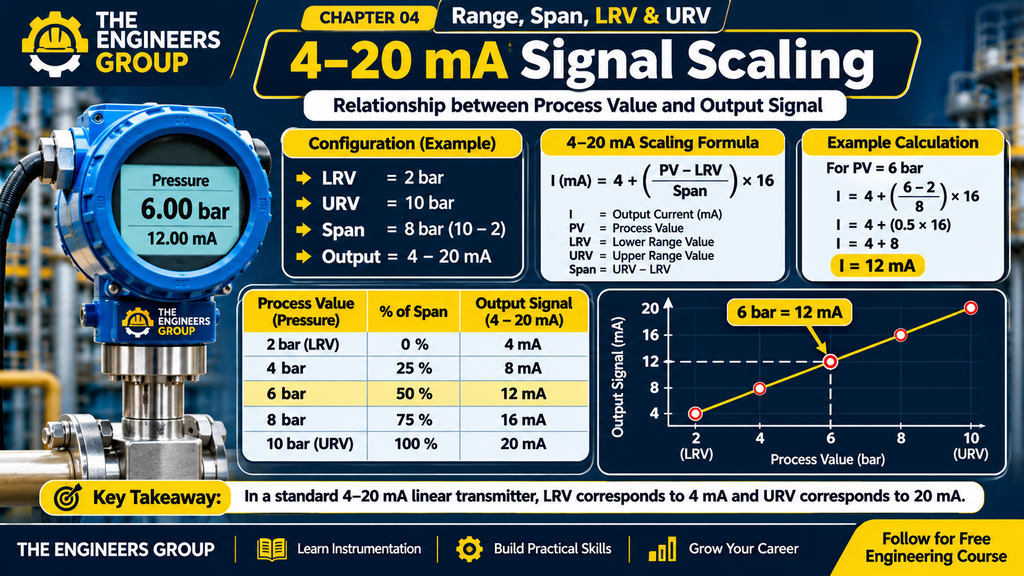
For a standard direct-acting linear transmitter:
- At LRV, output = 4 mA.
- At 25% of span, output = 8 mA.
- At 50% of span, output = 12 mA.
- At 75% of span, output = 16 mA.
- At URV, output = 20 mA.
Example:
A pressure transmitter has:
- LRV = 2 bar
- URV = 10 bar
- Output = 4–20 mA
| Pressure | Percentage of Span | Output |
|---|---|---|
| 2 bar | 0% | 4 mA |
| 4 bar | 25% | 8 mA |
| 6 bar | 50% | 12 mA |
| 8 bar | 75% | 16 mA |
| 10 bar | 100% | 20 mA |
This is the ideal linear relationship.
8. Practical Calculation – Finding Span
Suppose an industrial pressure transmitter has:
LRV = 5 bar
URV = 25 bar
Step 1: Apply the formula.
Span = URV − LRV
Step 2: Substitute the values.
Span = 25 − 5
Step 3: Calculate.
Span = 20 bar.
Therefore, the transmitter span is 20 bar.
9. Practical Calculation – Finding 4–20 mA Output
Consider a pressure transmitter with:
- LRV = 2 bar
- URV = 10 bar
- Actual Pressure = 6 bar
- Output Signal = 4–20 mA
Step 1: Calculate the span.
Span = 10 − 2 = 8 bar.
Step 2: Calculate the percentage of span.
Percentage = [(Actual Value − LRV) / Span] × 100
Percentage = [(6 − 2) / 8] × 100
Percentage = 50%.
Step 3: Calculate the output current.
Output = 4 + (Percentage / 100 × 16)
Output = 4 + (0.5 × 16)
Output = 4 + 8
Output = 12 mA.
Therefore, when the pressure is 6 bar, the ideal transmitter output is 12 mA.
10. What is Zero Suppression?
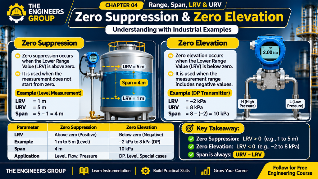
Zero suppression occurs when the lower range value (LRV) is above zero.
Example:
A level transmitter is installed on a tank with:
- LRV = 1 metre
- URV = 5 metres
Span = 5 − 1 = 4 metres.
Here, the lower range value is above zero.
This is an example of zero suppression.
Zero suppression is commonly encountered in level measurement applications, especially when the transmitter is installed below the lower measurement reference point.
11. What is Zero Elevation?
Zero elevation occurs when the lower range value (LRV) is below zero.
Example:
A differential pressure transmitter is configured for:
- LRV = −2 kPa
- URV = 8 kPa
Span = 8 − (−2)
Span = 10 kPa.
Here, the lower range value is below zero.
This is an example of zero elevation.
Zero elevation can occur in certain differential pressure and level measurement installations depending on the installation geometry and pressure reference.
12. What is Turndown Ratio?
Turndown ratio describes the ratio between the maximum calibrated span available for a transmitter and the minimum calibrated span over which it can still meet its specified performance.
Example:
Suppose a transmitter has:
- Maximum calibrated span = 100 bar
- Minimum specified calibrated span = 10 bar
Turndown Ratio = 100 / 10
Turndown Ratio = 10:1.
This means the transmitter can be configured over a span as small as one-tenth of its maximum calibrated span while meeting the stated performance specification.
Important: Always check the manufacturer’s datasheet for the permitted range, turndown and accuracy at the selected span.
13. Practical Industrial Example – Pressure Transmitter Configuration
Consider a pressure transmitter installed in an industrial pipeline.
Transmitter Configuration:
- Measurement Type = Pressure
- LRV = 0 bar
- URV = 16 bar
- Output Signal = 4–20 mA
- Actual Pressure = 8 bar
Calculation:
Span = 16 − 0 = 16 bar.
Percentage of Span = (8 / 16) × 100 = 50%.
Output = 4 + (50 / 100 × 16)
Output = 12 mA.
Therefore, at 8 bar, the ideal transmitter output is 12 mA.
An Instrument Technician can verify this output using a suitable loop calibrator or milliamp meter, following the approved testing and safety procedure.
14. Why Are Range, Span, LRV and URV Important?
These concepts are important in industrial instrumentation for several reasons.
1. Transmitter Configuration
Technicians use LRV and URV to configure the measurement range of smart transmitters.
2. Instrument Calibration
Calibration checks whether the instrument produces the expected output at different points across its configured range.
3. 4–20 mA Signal Verification
Understanding span helps technicians calculate the expected current output for a given process value.
4. PLC and DCS Scaling
PLC and DCS engineers use configured ranges to scale analogue input signals into engineering units.
5. Troubleshooting
Incorrect LRV or URV settings can cause incorrect process readings and output signals.
15. Common Mistakes Made by Instrument Technicians
- Confusing range with span.
- Assuming URV is always equal to span.
- Forgetting to subtract LRV when calculating span.
- Entering incorrect LRV and URV during transmitter configuration.
- Assuming every 4–20 mA transmitter uses a 0–100% measurement range.
- Ignoring the manufacturer’s measurement limits.
- Confusing zero suppression with zero elevation.
16. Instrument Technician Interview Questions and Answers
Q1. What is instrument range?
Answer: Instrument range is the configured or specified measurement interval between the lower and upper measurement limits.
Q2. What is span?
Answer: Span is the difference between URV and LRV.
Q3. What is LRV?
Answer: LRV is the lowest value of the configured measurement range.
Q4. What is URV?
Answer: URV is the highest value of the configured measurement range.
Q5. What is the formula for span?
Answer: Span = URV − LRV.
Q6. A transmitter has a range of 0–100 bar. What is its span?
Answer: Span = 100 − 0 = 100 bar.
Q7. A transmitter has an LRV of 10 bar and a URV of 50 bar. What is its span?
Answer: Span = 50 − 10 = 40 bar.
Q8. What is zero suppression?
Answer: Zero suppression occurs when the configured LRV is above zero.
Q9. What is zero elevation?
Answer: Zero elevation occurs when the configured LRV is below zero.
Q10. What is turndown ratio?
Answer: Turndown ratio is the ratio of the maximum calibrated span to the minimum calibrated span that meets the specified performance.
Q11. What is the standard output at LRV for a direct-acting 4–20 mA transmitter?
Answer: 4 mA.
Q12. What is the standard output at URV for a direct-acting 4–20 mA transmitter?
Answer: 20 mA.
Q13. A transmitter has a range of 2–10 bar. What is its span?
Answer: 10 − 2 = 8 bar.
Q14. What will be the output at 50% of span for a standard 4–20 mA transmitter?
Answer: 12 mA.
Q15. Why are LRV and URV important?
Answer: They define the configured measurement limits and determine the relationship between process values and transmitter output.
17. Multiple Choice Questions (MCQs)
Q1. What does LRV stand for?
A. Lower Range Value
B. Linear Range Variable
C. Low Reading Voltage
D. Level Range Value
Correct Answer: A. Lower Range Value
Q2. What does URV stand for?
A. Upper Reading Voltage
B. Upper Range Value
C. Unit Range Variable
D. Universal Range Value
Correct Answer: B. Upper Range Value
Q3. What is the formula for span?
A. LRV + URV
B. LRV × URV
C. URV − LRV
D. URV / LRV
Correct Answer: C. URV − LRV
Q4. A transmitter has a range of 0–10 bar. What is its span?
A. 5 bar
B. 10 bar
C. 20 bar
D. 0 bar
Correct Answer: B. 10 bar
Q5. A transmitter has LRV = 2 bar and URV = 12 bar. What is its span?
A. 8 bar
B. 10 bar
C. 12 bar
D. 14 bar
Correct Answer: B. 10 bar
Q6. What is the standard output at LRV for a direct-acting 4–20 mA transmitter?
A. 0 mA
B. 4 mA
C. 12 mA
D. 20 mA
Correct Answer: B. 4 mA
Q7. What is the output at 50% of span?
A. 4 mA
B. 8 mA
C. 12 mA
D. 20 mA
Correct Answer: C. 12 mA
Q8. Zero suppression occurs when:
A. LRV is above zero
B. LRV is below zero
C. URV is zero
D. Span is zero
Correct Answer: A. LRV is above zero
Q9. Zero elevation occurs when:
A. LRV is above zero
B. LRV is below zero
C. URV is above zero
D. Span is maximum
Correct Answer: B. LRV is below zero
Q10. A transmitter has a maximum calibrated span of 100 bar and a minimum calibrated span of 10 bar. What is its turndown ratio?
A. 2:1
B. 5:1
C. 10:1
D. 20:1
Correct Answer: C. 10:1
18. Chapter Summary
In this chapter, we learned four important concepts used in industrial instrumentation.
- Range is the complete configured measurement interval.
- Span is the difference between URV and LRV.
- LRV is the lowest configured measurement value.
- URV is the highest configured measurement value.
- Zero suppression occurs when LRV is above zero.
- Zero elevation occurs when LRV is below zero.
- Turndown ratio describes the available calibrated span range.
- For a standard direct-acting 4–20 mA transmitter, LRV corresponds to 4 mA and URV corresponds to 20 mA.
Understanding these concepts is essential for transmitter configuration, calibration, commissioning and troubleshooting.
19. What Is Next?
CHAPTER 05: Zero, Span & Calibration Basics
In the next chapter, we will learn:
- What is Zero in Instrumentation?
- What is Span Adjustment?
- Zero Calibration
- Span Calibration
- Zero and Span Errors
- Practical Transmitter Calibration
- Interview Questions and MCQs
Continue learning with THE ENGINEERS GROUP – Your Free Industrial Instrumentation Learning Platform.
Learn. Practice. Improve. Grow.
CONNECT WITH THE ENGINEERS GROUP
Learn. Practice. Improve. Grow.
📘 BUY INSTRUMENTATION E-BOOK 💬 CONTACT US ON WHATSAPP ▶️ SUBSCRIBE ON YOUTUBE f FOLLOW US ON FACEBOOKTHE ENGINEERS GROUP
Free Engineering Education for Everyone