
PLC Programming Course – Chapter 03: PLC Architecture and Hardware Components
PLC Programming Course – Chapter 03
Table of Contents
- Introduction to PLC Architecture
- What Is PLC Architecture?
- Basic PLC Architecture Diagram
- PLC Power Supply
- Central Processing Unit (CPU)
- PLC Memory
- Digital Input Module
- Digital Output Module
- Analog Input Module
- Analog Output Module
- PLC Communication Modules
- PLC Rack and Backplane
- Compact PLC vs Modular PLC
- Practical PLC Hardware Configuration
- How to Select the Right PLC Hardware
- Advantages of Modular PLC Architecture
- Common PLC Hardware Problems
- Important PLC Hardware Terminology
- PLC Architecture Interview Questions and Answers
- PLC Architecture MCQs
- Chapter Summary
- What You Will Learn in Chapter 04
1. Introduction to PLC Architecture
PLC (Programmable Logic Controller) is an important component of modern industrial automation systems. It is used to monitor input signals, execute control programs, and operate output devices in industrial applications.
To understand PLC programming properly, it is important to understand PLC Architecture and its hardware components.
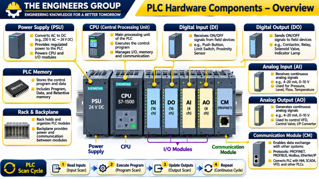
A PLC is not just a single electronic device. It is a complete control system consisting of different hardware modules such as:
- Power Supply
- Central Processing Unit (CPU)
- Memory
- Digital Input Modules
- Digital Output Modules
- Analog Input Modules
- Analog Output Modules
- Communication Modules
- Rack and Backplane
Each component performs a specific function. All these components work together to control industrial machines and processes.
For example, in an industrial motor control application, a PLC receives signals from push buttons and sensors, processes the programmed logic, and sends output signals to a motor starter or Variable Frequency Drive (VFD).
Understanding these components helps technicians and engineers troubleshoot PLC systems, select suitable hardware, and design reliable automation systems.
2. What Is PLC Architecture?
PLC Architecture refers to the internal structure and arrangement of different hardware components that make up a Programmable Logic Controller.
It explains how the CPU, power supply, memory, input/output modules, and communication interfaces are connected and how they work together.
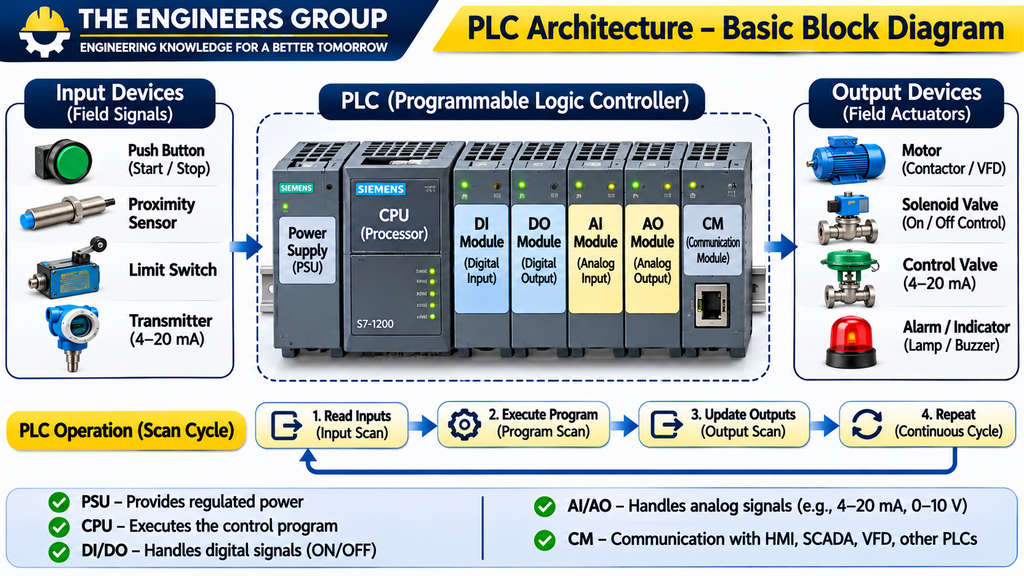
A typical PLC architecture follows this basic process:
- Input devices send signals to the PLC.
- Input modules receive and process these signals.
- The CPU reads the input status.
- The CPU executes the stored control program.
- Output modules update their output signals.
- Connected field devices perform the required action.
The complete operation is repeated continuously during PLC operation.
3. Basic PLC Architecture Diagram
A basic PLC architecture can be represented as follows:
Input Devices → Input Modules → CPU and Memory → Output Modules → Output Devices
Additional communication modules allow the PLC to exchange data with other industrial devices.
| Component | Main Function |
|---|---|
| Power Supply | Provides operating power to PLC electronics |
| CPU | Executes the control program |
| Memory | Stores programs, data and system information |
| Digital Input | Receives ON/OFF signals |
| Digital Output | Controls ON/OFF devices |
| Analog Input | Receives continuous signals |
| Analog Output | Sends continuous control signals |
| Communication Module | Exchanges data with external devices |
| Rack/Backplane | Holds modules and provides internal connections |
Important: The exact architecture depends on the PLC manufacturer and model. Compact PLCs may contain several functions in one housing, while modular PLCs use separate modules.
4. PLC Power Supply
The Power Supply is responsible for providing the required electrical power to the PLC system.
Most industrial PLC systems operate using a specified DC supply internally. Some PLC power supply units accept AC input and convert it into regulated DC power.
For example, a PLC power supply may accept 230 V AC and provide 24 V DC or another specified internal voltage, depending on the PLC model.
Main Functions of PLC Power Supply
- Converts incoming electrical power into the required DC supply.
- Provides stable voltage to PLC electronics.
- Supplies power to the CPU and supported modules.
- Helps protect the PLC system against specified power disturbances.
Common PLC Power Supply Ratings
| Input Supply | Output Supply | Application |
|---|---|---|
| 230 V AC | 24 V DC | Industrial PLC systems |
| 120 V AC | Manufacturer-specific DC | Certain PLC systems |
| 24 V DC | Internal regulated supply | DC-powered PLCs |
These are examples only. Always check the manufacturer’s technical datasheet.
Important Power Supply Checks
During PLC troubleshooting, check:
- Incoming supply voltage.
- Output DC voltage.
- Power supply status LED.
- Loose power terminals.
- Fuse and circuit protection.
- Overload conditions.
- Grounding and wiring connections.
Practical Example:
If the PLC CPU is not powering ON, first verify the incoming supply and power supply output. Check the power supply status indicators and wiring before assuming that the CPU is faulty.
5. Central Processing Unit (CPU)
The CPU is the main processing unit of a PLC. It controls the overall operation of the programmable logic controller.
The CPU receives input information, executes the user program, processes data, and updates output commands.
It also manages internal communication and diagnostic functions.
Main Functions of PLC CPU
- Reads input information.
- Executes the control program.
- Performs logical and mathematical operations.
- Updates output status.
- Manages memory.
- Communicates with supported devices.
- Monitors system diagnostics and faults.
PLC Scan Cycle
The PLC CPU generally performs its control operation through a repeated scan cycle.
The basic scan cycle includes:
1. Input Scan: The PLC reads the status of input devices.
2. Program Execution: The CPU executes the user program according to its programming structure.
3. Output Update: The PLC updates the output states.
4. Communication and Diagnostics: The PLC performs communication and system-related tasks as supported by its architecture.
The exact execution order varies between PLC platforms and configurations.
💬 NEED GUIDANCE IN PLC?
Contact THE ENGINEERS GROUP for eBook details, course information and learning support.
MESSAGE US ON WHATSAPPExample: Motor Start and Stop Logic
Suppose a motor is controlled through a PLC.
Inputs:
- Start Push Button
- Stop Push Button
- Overload Relay Feedback
Output:
- Motor Contactor
The CPU checks the input conditions and executes the motor control logic. If the start conditions are satisfied and no stop or overload condition exists, the PLC activates the motor contactor output.
6. PLC Memory
PLC Memory is used to store the control program, configuration data, process values, and other information required for PLC operation.
Different PLC platforms use different memory technologies and memory organizations.
Types of PLC Memory
6.1 Program Memory
Program memory stores the user-developed control program.
For example:
- Ladder Logic
- Function Block Diagram
- Structured Text
6.2 Data Memory
Data memory stores values used during program execution.
Examples include:
- Timer values
- Counter values
- Process variables
- Internal flags
- Mathematical results
6.3 Retentive Memory
Retentive memory preserves selected data after power loss, depending on the PLC configuration and memory technology.
Examples:
- Production counters
- Selected process settings
- Recipe values
6.4 Non-Retentive Memory
Non-retentive memory may lose or reset its stored values after power interruption or restart, depending on the PLC configuration.
Important Memory Terms
| Term | Meaning |
|---|---|
| RAM | Random Access Memory |
| ROM | Read Only Memory |
| Flash Memory | Non-volatile electronic memory |
| Retentive Memory | Retains selected data after power loss |
| Program Memory | Stores user control program |
| Data Memory | Stores operating data and variables |
7. Digital Input Module
A Digital Input Module receives ON/OFF signals from field devices and transfers their status to the PLC CPU.
Digital signals have two basic states:
- ON (Logic 1)
- OFF (Logic 0)
Digital inputs are commonly used for push buttons, selector switches, limit switches, proximity sensors, and auxiliary contacts.
Common Digital Input Devices
| Device | Application |
|---|---|
| Start Push Button | Motor start command |
| Stop Push Button | Motor stop command |
| Limit Switch | Position detection |
| Proximity Sensor | Object detection |
| Float Switch | Level indication |
| Overload Contact | Motor protection feedback |
Digital Input Module Types
DC Digital Input Module
Commonly used with DC sensors and control circuits, such as 24 V DC devices.
AC Digital Input Module
Used with compatible AC field signals.
Sinking and Sourcing Inputs
Digital input wiring may use sinking or sourcing arrangements.
In a common 24 V DC PNP sensor arrangement, the sensor supplies positive voltage to the input when activated. In a common NPN arrangement, the sensor switches the input toward 0 V.
Always follow the PLC input module wiring diagram and sensor specifications.
Practical Example:
When an operator presses a Start Push Button, the digital input module detects the signal and makes the corresponding input status available to the PLC program.
8. Digital Output Module
A Digital Output Module sends ON/OFF control signals from the PLC to field devices.
It allows the PLC to operate devices such as contactors, relays, indicator lamps, solenoid valves, and alarms.
Common Digital Output Devices
| Device | Application |
|---|---|
| Contactor | Motor switching |
| Relay | Electrical switching |
| Solenoid Valve | Fluid control |
| Indicator Lamp | Status indication |
| Buzzer | Audible alarm |
| Interposing Relay | Interface between PLC and load |
Types of Digital Output Modules
8.1 Relay Output
Relay output modules use electrical contacts to switch compatible AC or DC loads within their specified ratings.
Advantages:
- Can switch compatible AC and DC loads.
- Provides electrical contact isolation.
- Suitable for certain switching applications.
Limitations:
- Mechanical contact wear.
- Slower switching compared with semiconductor outputs.
- Limited switching life.
8.2 Transistor Output
Transistor output modules are generally used for DC switching applications.
Advantages:
- Fast switching.
- No mechanical contacts.
- Suitable for high-speed applications within module ratings.
8.3 Triac Output
Triac output modules are used for compatible AC switching applications.
They are suitable for certain AC loads but have specific electrical limitations.
Important: Never connect a field load directly to a PLC output without checking the output type, voltage, current rating, and load compatibility.
9. Analog Input Module
An Analog Input Module receives continuous signals from field instruments and converts them into digital values that the PLC CPU can process.
Unlike digital signals, analog signals represent a range of values.
Common industrial analog signal types include:
- 4–20 mA
- 0–20 mA
- 0–10 V
- 1–5 V
Common Analog Input Devices
| Instrument | Measurement |
|---|---|
| Pressure Transmitter | Pressure |
| Temperature Transmitter | Temperature |
| Level Transmitter | Liquid level |
| Flow Transmitter | Flow rate |
| Load Cell Transmitter | Weight or force |
Example: 4–20 mA Pressure Transmitter
Suppose a pressure transmitter has the following range:
LRV = 0 bar
URV = 10 bar
Signal range = 4–20 mA
At 4 mA, the pressure is 0 bar.
At 20 mA, the pressure is 10 bar.
If the transmitter output is 12 mA:
Measured pressure = [(12 − 4) / (20 − 4)] × 10
Measured pressure = (8 / 16) × 10
Measured Pressure = 5 bar
This is a basic linear scaling example.
The PLC analog input module receives the current signal and provides a corresponding digital value to the CPU.
10. Analog Output Module
An Analog Output Module generates continuous control signals from the PLC.
These signals are used to control devices that require variable commands rather than simple ON/OFF operation.
Common analog output signals include:
- 4–20 mA
- 0–20 mA
- 0–10 V
Common Analog Output Applications
| Device | Control Application |
|---|---|
| VFD | Motor speed reference |
| Control Valve Positioner | Valve opening command |
| I/P Converter | Electrical-to-pneumatic signal conversion |
| Power Controller | Power regulation |
Practical Example: VFD Speed Control
Suppose a PLC sends a 4–20 mA signal to a compatible VFD.
4 mA = 0% speed reference
20 mA = 100% speed reference
12 mA = 50% speed reference
The VFD interprets this signal according to its configured scaling and controls the motor speed accordingly.
Note: Actual motor speed also depends on the VFD configuration, motor characteristics, operating limits, and process conditions.
11. PLC Communication Modules
Communication Modules allow PLCs to exchange information with other industrial devices and automation systems.
Modern industrial automation systems use communication networks to connect PLCs, HMIs, SCADA systems, remote I/O stations, VFDs, and other controllers.
Common Industrial Communication Protocols
11.1 Modbus RTU
Modbus RTU is a serial communication protocol commonly used over RS-485 networks.
It is widely used for communication between PLCs, energy meters, VFDs, and instruments.
11.2 Modbus TCP
Modbus TCP is an Ethernet-based implementation of Modbus communication.
It is used for communication between compatible Ethernet devices.
11.3 PROFINET
PROFINET is an industrial Ethernet communication standard used in automation systems.
It supports communication between PLCs, remote I/O, drives, and other industrial devices.
11.4 PROFIBUS
PROFIBUS is an industrial fieldbus communication standard used in process and factory automation.
11.5 EtherNet/IP
EtherNet/IP is an industrial communication protocol built on standard Ethernet technologies.
It is used for data exchange between compatible industrial automation devices.
Communication Module Applications
- PLC to PLC communication.
- PLC to HMI communication.
- PLC to SCADA communication.
- PLC to VFD communication.
- Remote I/O communication.
- Industrial network integration.
12. PLC Rack and Backplane
In modular PLC systems, the Rack is the physical structure that holds the PLC modules.
The Backplane provides the internal electrical and communication connections between compatible modules.
Main Functions of PLC Rack
- Holds PLC modules securely.
- Provides a mounting arrangement.
- Supports module organization.
- Allows expansion using compatible modules.
Main Functions of Backplane
- Provides internal communication paths.
- Distributes supported power to modules.
- Connects the CPU with I/O and other modules.
Some compact PLCs do not use a traditional separate rack and backplane because their components are integrated into a single unit.
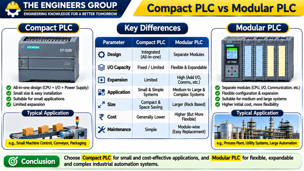
13. Compact PLC vs Modular PLC
PLC systems are available in different hardware configurations.
Two common types are Compact PLC and Modular PLC.
Compact PLC
A Compact PLC contains major components such as CPU, power supply, and a fixed number of I/O points in one integrated housing.
Advantages:
- Compact design.
- Easy installation.
- Suitable for small automation applications.
- Generally lower hardware complexity.
Limitations:
- Limited expansion options.
- Fixed or restricted I/O configuration.
- Less flexibility for large systems.
Modular PLC
A Modular PLC uses separate hardware modules that can be selected and installed according to application requirements.
Advantages:
- Flexible configuration.
- Expandable I/O.
- Supports a wide range of communication modules.
- Suitable for complex automation applications.
Limitations:
- Higher hardware cost in many configurations.
- Requires more installation space.
- Requires proper module selection and configuration.
Comparison Table
| Parameter | Compact PLC | Modular PLC |
|---|---|---|
| Design | Integrated | Separate modules |
| Installation | Simple | Requires module arrangement |
| Expansion | Limited | More flexible |
| I/O | Usually fixed or limited | Configurable |
| Application | Small systems | Medium and large systems |
| Flexibility | Lower | Higher |
14. Practical PLC Hardware Configuration
Let’s understand a basic industrial motor control application using PLC hardware.
Application: Automatic Motor Start and Stop Control
Required Hardware:
| Component | Quantity | Function |
|---|---|---|
| PLC CPU | 1 | Executes control logic |
| Power Supply | 1 | Supplies PLC power |
| Digital Input Module | 1 | Receives push button and feedback signals |
| Digital Output Module | 1 | Controls motor contactor circuit |
| Start Push Button | 1 | Motor start command |
| Stop Push Button | 1 | Motor stop command |
| Overload Relay Auxiliary Contact | 1 | Overload feedback |
| Contactor | 1 | Switches motor power circuit |
| Indicator Lamp | 1 | Motor status indication |
Working Principle
- The operator presses the Start Push Button.
- The PLC digital input module detects the input.
- The CPU executes the programmed logic.
- If the stop and overload conditions are healthy, the PLC activates the digital output.
- The output operates the motor contactor control circuit.
- The contactor closes its main contacts and supplies power to the motor.
- If the Stop Push Button is pressed or an overload trip occurs, the PLC removes the run command according to the control logic.
Important Safety Note: Motor power switching and overload protection must be designed using appropriately rated electrical equipment. Emergency stop and safety functions must use suitable safety-rated circuits and devices; a standard PLC alone should not be treated as a safety controller.
15. How to Select the Right PLC Hardware
Selecting the correct PLC hardware is important for reliable industrial automation.
Consider the following factors:
1. Number of Inputs
Calculate how many digital and analog input signals are required.
2. Number of Outputs
Identify how many digital and analog outputs are needed.
3. Communication Requirements
Check whether the application requires PROFINET, Modbus, PROFIBUS, EtherNet/IP, or other protocols.
4. CPU Performance
Select a CPU according to program size, processing requirements, communication load, and application complexity.
5. Expansion Requirements
Consider future expansion and additional I/O requirements.
6. Environmental Conditions
Check operating temperature, humidity, vibration, electrical noise, and enclosure requirements.
7. Manufacturer Compatibility
Verify module compatibility, firmware requirements, software support, and communication interfaces.
16. Advantages of Modular PLC Architecture
Modular PLC architecture provides several advantages in industrial applications.
- Flexible hardware configuration.
- Easy expansion of input and output points.
- Simple replacement of faulty modules.
- Better system organization.
- Support for different communication modules.
- Easier maintenance and troubleshooting.
- Suitable for complex industrial automation systems.
17. Common PLC Hardware Problems
PLC hardware problems can affect machine operation and production.
Understanding common faults helps technicians troubleshoot systems efficiently.
| Problem | Possible Cause | Basic Check |
|---|---|---|
| PLC Not Powering ON | Supply failure | Check input and output voltage |
| CPU Fault LED | CPU or configuration fault | Check diagnostics |
| Input Not Working | Sensor or wiring fault | Check sensor signal and input LED |
| Output Not Working | Output module or load fault | Check output status and load circuit |
| Analog Reading Incorrect | Scaling or wiring problem | Verify signal and configuration |
| Communication Failure | Network or configuration issue | Check cable, IP and protocol settings |
| Module Fault | Module or connection problem | Check module diagnostics and seating |
Troubleshooting Tip: Always check the PLC diagnostic buffer, module status indicators, wiring diagrams, and manufacturer documentation before replacing hardware.
18. Important PLC Hardware Terminology
| Term | Full Form / Meaning |
|---|---|
| PLC | Programmable Logic Controller |
| CPU | Central Processing Unit |
| DI | Digital Input |
| DO | Digital Output |
| AI | Analog Input |
| AO | Analog Output |
| I/O | Input/Output |
| HMI | Human Machine Interface |
| SCADA | Supervisory Control and Data Acquisition |
| VFD | Variable Frequency Drive |
| PSU | Power Supply Unit |
| RAM | Random Access Memory |
| ROM | Read Only Memory |
| RTU | Remote Terminal Unit |
| PLC Rack | Structure for mounting modules |
| Backplane | Internal module connection system |
19. PLC Architecture Interview Questions and Answers
Q1. What is PLC Architecture?
PLC Architecture is the arrangement of hardware components such as CPU, memory, power supply, input modules, output modules, and communication modules.
Q2. What is the main function of a PLC CPU?
The CPU executes the control program, processes input information, updates outputs, and manages PLC operations.
Q3. What is the function of a PLC power supply?
It provides the required electrical power to PLC electronics and compatible modules.
Q4. What is the function of PLC memory?
PLC memory stores the control program, data, configuration information, and process values.
Q5. What is a Digital Input Module?
It receives ON/OFF signals from field devices such as push buttons, limit switches, and proximity sensors.
Q6. What is a Digital Output Module?
It sends ON/OFF control signals to devices such as relays, contactors, and solenoid valves.
Q7. What is an Analog Input Module?
It receives continuous electrical signals, such as 4–20 mA or 0–10 V, from field instruments.
Q8. What is an Analog Output Module?
It generates continuous control signals to operate devices such as VFDs and control valve positioners.
Q9. What is the difference between Digital and Analog Signals?
Digital signals represent discrete states, usually ON and OFF. Analog signals represent continuously varying values within a defined range.
Q10. What is the difference between AI and DI?
AI receives continuous analog signals, while DI receives discrete ON/OFF signals.
Q11. What is the difference between AO and DO?
AO generates continuous output signals, while DO generates discrete ON/OFF output signals.
Q12. What is a Communication Module?
It enables the PLC to exchange data with other automation devices and industrial networks.
Q13. What is a PLC Rack?
A PLC rack is a structure used to mount and organize modules in modular PLC systems.
Q14. What is a Backplane?
A backplane provides internal electrical and communication connections between compatible PLC modules.
Q15. What is a Compact PLC?
A Compact PLC integrates major components such as CPU and I/O into a single housing.
Q16. What is a Modular PLC?
A Modular PLC uses separate modules that can be selected and expanded according to application requirements.
Q17. What is a 4–20 mA Signal?
It is a common industrial analog current signal used to transmit process measurements from instruments to controllers.
Q18. Why are Transistor Outputs used?
Transistor outputs provide fast switching for compatible DC loads and applications.
Q19. What is the function of a Relay Output Module?
It switches compatible electrical loads using mechanical relay contacts.
Q20. What should you check if a PLC input is not working?
Check the field device, supply voltage, wiring, terminal connections, input module status LED, and PLC diagnostics.
20. PLC Architecture MCQs
Q1. What is the main processing unit of a PLC?
A. Power Supply
B. CPU
C. Input Module
D. Output Module
Correct Answer: B. CPU
Q2. Which PLC component stores the control program?
A. Contactor
B. Sensor
C. Memory
D. Terminal Block
Correct Answer: C. Memory
Q3. Which module receives ON/OFF signals?
A. Analog Output
B. Digital Input
C. Analog Input
D. Communication Module
Correct Answer: B. Digital Input
Q4. Which module receives a 4–20 mA signal?
A. Digital Input
B. Digital Output
C. Analog Input
D. Power Supply
Correct Answer: C. Analog Input
Q5. Which module sends a variable analog signal to a VFD?
A. Digital Input
B. Analog Output
C. Digital Output
D. CPU
Correct Answer: B. Analog Output
Q6. Which device is commonly controlled by a Digital Output Module?
A. Pressure Transmitter
B. RTD Sensor
C. Contactor
D. Flow Transmitter
Correct Answer: C. Contactor
Q7. What is the main function of a PLC power supply?
A. Execute the program
B. Provide electrical power
C. Measure temperature
D. Control communication protocols
Correct Answer: B. Provide electrical power
Q8. Which communication protocol is commonly used over RS-485?
A. Modbus RTU
B. HDMI
C. USB Audio
D. VGA
Correct Answer: A. Modbus RTU
Q9. Which output type is commonly used for fast DC switching?
A. Relay
B. Transistor
C. Transformer
D. Fuse
Correct Answer: B. Transistor
Q10. What is the function of a PLC backplane?
A. Measure pressure
B. Connect compatible modules internally
C. Control motor speed directly
D. Display process values
Correct Answer: B. Connect compatible modules internally
Q11. Which device detects object presence without physical contact?
A. Proximity Sensor
B. Contactor
C. Circuit Breaker
D. Relay
Correct Answer: A. Proximity Sensor
Q12. Which PLC configuration generally provides more flexible hardware expansion?
A. Compact PLC
B. Modular PLC
C. Mechanical Timer
D. Manual Switch
Correct Answer: B. Modular PLC
Q13. What does AI stand for in PLC terminology?
A. Automatic Indicator
B. Analog Input
C. Active Interface
D. Automatic Installation
Correct Answer: B. Analog Input
Q14. What is the purpose of a PLC communication module?
A. Store mechanical energy
B. Exchange data with external devices
C. Measure motor temperature directly
D. Protect the motor from overload
Correct Answer: B. Exchange data with external devices
Q15. Which PLC component executes the user control logic?
A. CPU
B. Power Supply
C. Rack
D. Terminal Block
Correct Answer: A. CPU
FREE 100 PLC INTERVIEW Q&A PDF DOWNLOAD
Download your free PLC learning material.
📥 DOWNLOAD FREE PLC PDFTHE ENGINEERS GROUP
21. Chapter Summary
In this chapter, we learned about PLC Architecture and its major hardware components.
We covered the functions of the power supply, CPU, memory, digital input modules, digital output modules, analog input modules, analog output modules, communication modules, rack, and backplane.
We also explored Compact PLC versus Modular PLC, practical motor control hardware configuration, PLC hardware selection, and common troubleshooting methods.
Understanding PLC hardware is essential before learning advanced PLC programming and industrial automation applications.
22. What You Will Learn in Chapter 04
In the next chapter, we will study:
PLC Input and Output (I/O) System – Digital and Analog I/O Explained
Topics will include:
- Digital Input and Output Addressing
- Analog Input and Output Processing
- PNP and NPN Sensor Wiring
- Sinking and Sourcing Concepts
- PLC I/O Addressing Examples
- Practical PLC Wiring Diagrams
- I/O Troubleshooting Techniques
Stay connected with THE ENGINEERS GROUP and continue learning industrial automation step by step.
THE ENGINEERS GROUP
ENGINEERING KNOWLEDGE FOR A BETTER TOMORROW
Learn. Practice. Grow.
CONNECT WITH THE ENGINEERS GROUP
Learn. Practice. Improve. Grow.
📘 EXPLORE OUR EBOOK 💬 CONTACT US ON WHATSAPP ▶️ SUBSCRIBE ON YOUTUBE FOLLOW US ON FACEBOOKTHE ENGINEERS GROUP
Free Engineering Education for Everyone