PLC Programming Complete Course – Chapter 01: Introduction to PLC
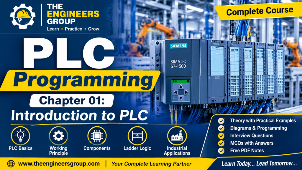
Table of Contents – Chapter 01: Introduction to PLC
- Introduction to PLC
- What is PLC?
- Basic Working Principle of PLC
- Main Components of PLC
- CPU (Central Processing Unit)
- Power Supply Module
- Input Module
- Output Module
- Memory
- Communication Port
- How Does a PLC Work?
- PLC vs Relay-Based Control System
- Advantages of PLC
- Applications of PLC in Industries
- Practical Industrial Example – Motor Start/Stop Control
- Important PLC Terminology
- PLC Interview Questions and Answers
- Multiple Choice Questions (MCQs)
- Chapter Summary
1. Introduction to PLC
The PLC Programming Course by THE ENGINEERS GROUP is designed for ITI, Diploma, B.Tech students, Instrument Technicians, Electrical Technicians, and Automation Engineers who want to learn industrial PLC programming from basic to advanced levels.
In modern industries, automation plays an important role in improving productivity, accuracy, safety, and operational efficiency. One of the most important devices used in industrial automation is the Programmable Logic Controller (PLC).
One of the most important devices used in industrial automation is the PLC (Programmable Logic Controller).
A PLC is an industrial digital controller designed to monitor input signals, execute programmed control logic, and operate output devices according to predefined instructions.
PLCs are widely used in:
- Manufacturing Industries
- Power Plants
- Oil and Gas Industries
- Water Treatment Plants
- Cement Industries
- Pharmaceutical Industries
- Food Processing Industries
- Automotive Industries
Before PLC technology became popular, industries mainly used relay-based control systems. These systems required extensive wiring and were difficult to modify. PLCs made industrial control systems more flexible, reliable, and easier to maintain.
2. What is PLC?
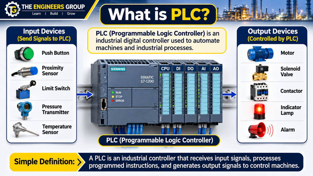
PLC stands for Programmable Logic Controller.
A Programmable Logic Controller is a rugged industrial computer used to automate machines and industrial processes.
It receives signals from input devices such as push buttons, proximity sensors, limit switches, pressure switches, and temperature transmitters.
The PLC processes these signals according to the user-written program and controls output devices such as motors, solenoid valves, contactors, indicator lamps, and alarms.
Simple Definition
A PLC is an industrial controller that receives input signals, processes programmed instructions, and generates output signals to control machines and industrial processes automatically.
This PLC Programming Course provides a strong foundation in PLC basics, PLC architecture, input and output modules, programming concepts, and industrial automation applications. It helps beginners understand how programmable logic controllers are used in real industrial environments.
💬 NEED GUIDANCE IN PLC ?
Contact THE ENGINEERS GROUP for eBook details, course information and learning support.
MESSAGE US ON WHATSAPPWhy is PLC Important?
PLCs are important because they allow industries to automate repetitive operations, reduce manual intervention, improve production efficiency, and maintain consistent machine operation.
3. Basic Working Principle of PLC
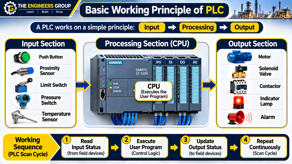
The working principle of a PLC is based on three basic operations:
- Input
- Processing
- Output
A. Input Section
The input section receives signals from field devices and sends their status to the PLC CPU through the input module.
Examples of input devices:
- Push Buttons
- Limit Switches
- Proximity Sensors
- Photoelectric Sensors
- Pressure Switches
- Temperature Switches
- Level Switches
These devices provide information about the condition of a machine or industrial process.
B. Processing Section
The CPU (Central Processing Unit) is the brain of the PLC.
It performs the following operations:
- Reads input status.
- Executes the user program.
- Performs logical operations.
- Processes timers and counters.
- Updates output status.
- Performs communication and diagnostic operations.
C. Output Section
The output section sends control signals to external devices according to the executed PLC program.
Examples of output devices:
- Motor Starters
- Contactors
- Solenoid Valves
- Relay Coils
- Indicator Lamps
- Alarm Systems
- Control Valves
The output devices perform actions according to the PLC control logic.
4. Main Components of PLC
A standard PLC system consists of several important components that work together to control industrial machines and processes.
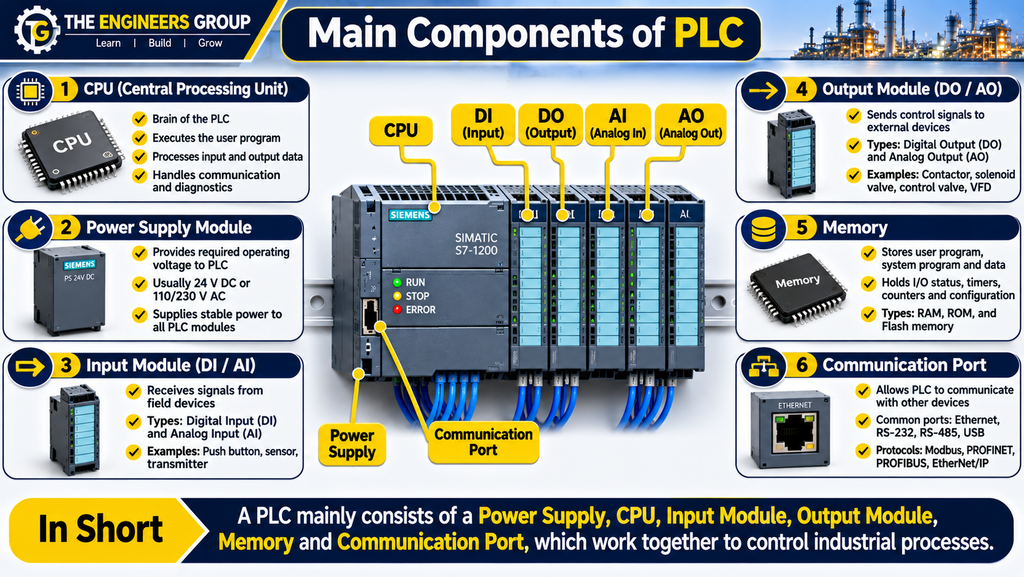
4.1 CPU (Central Processing Unit)
The CPU is the main processing unit of a PLC. It executes the user program and manages the overall operation of the controller.
Functions of CPU:
- Executing the control program.
- Processing input and output data.
- Performing mathematical calculations.
- Managing communication.
- Monitoring system operation.
- Handling diagnostic functions.
4.2 Power Supply Module
The power supply module provides the required operating voltage to PLC electronic components.
Depending on the PLC model, the supply may be 24 V DC or an AC input supply such as 120/230 V AC.
Its main function is to provide stable power to the PLC system.
4.3 Input Module
The input module receives signals from external field devices and converts them into signals that can be processed by the PLC CPU.
Common input types:
- Digital Input (DI)
- Analog Input (AI)
Examples include push buttons, proximity sensors, pressure transmitters, and temperature transmitters.
4.4 Output Module
The output module sends control signals from the PLC to external field devices.
Common output types:
- Digital Output (DO)
- Analog Output (AO)
Examples include contactors, solenoid valves, indicator lamps, and control valves.
4.5 Memory
PLC memory stores important information required for controller operation.
It may store:
- User Programs
- System Programs
- Input and Output Data
- Internal Variables
- Timer and Counter Values
- Configuration Information
4.6 Communication Port
Communication ports allow PLCs to communicate with other industrial devices and automation systems.
Common communication interfaces include:
- Ethernet
- RS-232
- RS-485
- USB
Common industrial communication protocols include:
- Modbus RTU
- Modbus TCP
- PROFINET
- PROFIBUS
- EtherNet/IP
5. How Does a PLC Work?
A PLC operates through a repetitive process known as the PLC Scan Cycle.
The basic operations are:
- Read Input Status.
- Execute the User Program.
- Update Output Status.
- Perform Communication and Diagnostic Tasks.
This process repeats continuously while the PLC is in RUN mode.
Example: Motor Start/Stop Application
Consider an industrial motor controlled through a PLC.
- When the START push button is pressed, the PLC receives an input signal.
- The CPU checks the programmed conditions.
- If all required conditions are satisfied, the PLC activates the motor output.
- When the STOP push button is pressed, the PLC deactivates the motor output.
- If an overload condition occurs, the motor is stopped according to the control and protection design.
The actual response depends on the PLC program, output configuration, and safety interlocks.
6. PLC vs Relay-Based Control System
Before PLCs became common in industrial automation, relay-based control systems were widely used for machine control.
The following table explains the major differences.
| Parameter | PLC System | Relay System |
|---|---|---|
| Control | Program-based | Hardware-based |
| Wiring | Comparatively less | More complex |
| Modification | Software changes | Wiring changes |
| Flexibility | High | Limited |
| Troubleshooting | Diagnostic tools | Manual checking |
| Timers | Built-in instructions | External timers |
| Counters | Built-in instructions | External counters |
| Maintenance | Easier in many applications | More wiring maintenance |
| Applications | Simple to complex automation | Mainly hardwired control |
7. Advantages of PLC
PLCs provide several advantages in modern industrial automation.
- High Reliability: PLCs are designed to operate in demanding industrial environments.
- Flexible Programming: Control logic can be modified through software.
- Reduced Wiring: PLC-based systems can reduce extensive control wiring.
- Easy Troubleshooting: Programming software provides monitoring and diagnostic tools.
- Faster Modification: Changes in machine logic can often be implemented without major rewiring.
- Compact Design: Multiple control functions can be performed using a single controller.
- Built-in Timers and Counters: PLCs provide instructions for timing and counting operations.
- Communication: PLCs can communicate with HMI and SCADA systems.
- Process Monitoring: Machine conditions can be monitored through PLC programming software.
- Automation: PLCs can control complex industrial processes automatically.
8. Applications of PLC in Industries
PLCs are used in almost every major industrial sector.
8.1 Manufacturing Industry
PLCs control automated production lines, assembly machines, packaging systems, and material handling equipment.
8.2 Water Treatment Plants
PLCs control pumps, valves, tank levels, filtration systems, and water treatment processes.
8.3 Power Plants
PLCs are used for auxiliary equipment control, monitoring, and automation.
8.4 Oil and Gas Industry
PLCs are used in process automation, equipment control, and monitoring systems. Safety-critical shutdown functions require appropriate safety-rated systems.
8.5 Cement Industry
PLCs control conveyors, crushers, motors, feeders, and material handling systems.
8.6 Pharmaceutical Industry
PLCs are used for automated production, batching, temperature control, and process monitoring.
8.7 Automotive Industry
PLCs control robotic assembly lines, welding machines, conveyors, and automated inspection systems.
9. Practical Industrial Example – Motor Start/Stop Control
Consider a three-phase induction motor controlled through a PLC.
Required Components
- PLC
- START Push Button
- STOP Push Button
- Motor Contactor
- Overload Relay
- Three-Phase Motor
- Control Power Supply
Working Operation
- The operator presses the START push button.
- The PLC receives the input signal.
- The PLC checks the STOP command and required permissive conditions.
- If all conditions are satisfied, the PLC energizes the contactor output.
- The contactor closes its main power contacts and the motor starts.
- When the STOP button is pressed, the PLC deactivates the contactor output.
- If an overload trip occurs, the motor stops through the configured protection circuit.
Important Safety Note: Motor overload protection and emergency stop functions must be designed appropriately. Emergency stop and other safety functions should not rely solely on an ordinary standard PLC program.
This is one of the most basic and important PLC applications in industrial automation.
10. Important PLC Terminology
| Term | Full Form / Meaning |
|---|---|
| PLC | Programmable Logic Controller |
| CPU | Central Processing Unit |
| DI | Digital Input |
| DO | Digital Output |
| AI | Analog Input |
| AO | Analog Output |
| HMI | Human Machine Interface |
| SCADA | Supervisory Control and Data Acquisition |
| I/O | Input/Output |
| Ladder Logic | Graphical PLC Programming Language |
| Scan Cycle | Repeated PLC Execution Process |
| VFD | Variable Frequency Drive |
| RTU | Remote Terminal Unit |
| NO | Normally Open |
| NC | Normally Closed |
11. PLC Interview Questions and Answers
Q1. What is PLC?
Answer: PLC stands for Programmable Logic Controller. It is an industrial digital controller used to automate machines and processes.
Q2. What is the full form of PLC?
Answer: Programmable Logic Controller.
Q3. What is the brain of a PLC?
Answer: CPU (Central Processing Unit) is the main processing unit of a PLC.
Q4. What are the three basic operations of PLC?
Answer: Input, Processing, and Output.
Q5. What is the function of a PLC input module?
Answer: It receives signals from external field devices such as sensors, push buttons, and switches.
Q6. What is the function of a PLC output module?
Answer: It sends control signals to external devices such as contactors, relays, and solenoid valves.
Q7. What is a PLC scan cycle?
Answer: It is the repetitive process in which the PLC reads input conditions, executes the user program, and updates outputs.
Q8. Why are PLCs used in industries?
Answer: PLCs provide reliable, flexible, and programmable control for industrial machines and processes.
Q9. What is the difference between digital and analog input?
Answer: Digital inputs represent discrete states, typically ON/OFF, whereas analog inputs represent continuously varying values such as pressure, temperature, and flow.
Q10. Can a PLC communicate with SCADA?
Answer: Yes. A PLC can communicate with SCADA using supported industrial communication protocols such as Modbus TCP, PROFINET, and EtherNet/IP.
Q11. What is the function of a PLC power supply?
Answer: It provides the required electrical power to the PLC electronic components.
Q12. What is Ladder Logic?
Answer: Ladder Logic is a graphical PLC programming language that uses contacts, coils, timers, counters, and other instructions to implement control logic.
Q13. What is the difference between PLC and a normal computer?
Answer: A PLC is specifically designed for industrial control, real-time operation, electrical noise immunity, and machine automation. A normal computer is designed for general-purpose computing.
Q14. What is a digital output?
Answer: A digital output provides a discrete control signal, typically ON or OFF, to operate external devices.
Q15. What is an analog output?
Answer: An analog output provides a continuously varying control signal, such as 4–20 mA or 0–10 V, depending on the module configuration.
12. Multiple Choice Questions (MCQs)
Test your understanding of PLC fundamentals with the following questions.
Q1. What is the full form of PLC?
A. Programmable Logic Controller
B. Power Logic Control
C. Process Level Controller
D. Programmable Load Circuit
Correct Answer: A. Programmable Logic Controller
Q2. Which component is known as the brain of PLC?
A. Power Supply
B. CPU
C. Input Module
D. Output Module
Correct Answer: B. CPU
Q3. Which device provides signals to PLC inputs?
A. Motor
B. Contactor
C. Proximity Sensor
D. Solenoid Valve
Correct Answer: C. Proximity Sensor
Q4. Which programming language is commonly used in PLCs?
A. HTML
B. Ladder Logic
C. CSS
D. SQL
Correct Answer: B. Ladder Logic
Q5. What does DI stand for?
A. Digital Input
B. Direct Indication
C. Data Information
D. Digital Instrument
Correct Answer: A. Digital Input
Q6. Which module sends signals to external devices?
A. Input Module
B. Output Module
C. Memory Module
D. Communication Module
Correct Answer: B. Output Module
Q7. Which device is commonly controlled by a PLC output?
A. Push Button
B. Proximity Sensor
C. Contactor
D. Limit Switch
Correct Answer: C. Contactor
Q8. What is the primary function of the PLC CPU?
A. Generate mechanical power
B. Execute the control program
C. Measure pressure directly
D. Supply three-phase power
Correct Answer: B. Execute the control program
Q9. Which of the following is an industrial communication protocol?
A. PROFINET
B. HTML
C. CSS
D. JPEG
Correct Answer: A. PROFINET
Q10. What does HMI stand for?
A. Human Machine Interface
B. High Motor Input
C. Hardware Module Installation
D. Human Monitoring Instrument
Correct Answer: A. Human Machine Interface
13. Chapter Summary
In this chapter, we learned the fundamentals of Programmable Logic Controllers (PLC), including their definition, working principle, major components, advantages, applications, and industrial examples.
We also understood the differences between PLC-based and relay-based control systems and explored basic PLC interview questions and MCQs.
A PLC is an essential device in modern industrial automation. Understanding PLC fundamentals is the first step toward learning advanced PLC programming, troubleshooting, and industrial automation systems.
FREE 100 PLC INTERVIEW Q&A PDF DOWNLOAD
Download your free PLC learning material.
📥 DOWNLOAD FREE PLC PDFTHE ENGINEERS GROUP
What Will You Learn in Chapter 02?
In the next chapter, we will study Industrial Automation – Fundamentals and Applications and understand how PLCs work together with sensors, actuators, HMI, SCADA, and other industrial automation devices.
THE ENGINEERS GROUP
Engineering Knowledge for a Better Tomorrow.
CONNECT WITH THE ENGINEERS GROUP
Learn. Practice. Improve. Grow.
📘 EXPLORE OUR EBOOK 💬 CONTACT US ON WHATSAPP ▶️ SUBSCRIBE ON YOUTUBE FOLLOW US ON FACEBOOKTHE ENGINEERS GROUP
Free Engineering Education for Everyone