
Zero, Span & Calibration Basics – Complete Guide for Instrument Technicians
📘 Chapter 05: Zero, Span & Calibration Basics
📑 Table of Contents
01. Introduction
- Introduction to Zero, Span and Calibration
02. Understanding Zero
- What is Zero in Instrumentation?
- What is Zero Adjustment?
03. Understanding Span
- What is Span in Instrumentation?
- What is Span Adjustment?
- Difference Between Zero Adjustment and Span Adjustment
04. Calibration Fundamentals
- What is Calibration?
- Difference Between Calibration and Adjustment
- What is an Instrument Calibration Standard?
05. Types of Instrument Calibration
- Pressure Transmitter Calibration
- Temperature Transmitter Calibration
- Differential Pressure Transmitter Calibration
- Level Transmitter Calibration
- Loop Calibration
06. Practical Calibration
- Practical Example – 4–20 mA Transmitter Calibration
- Step-by-Step Pressure Transmitter Calibration Procedure
07. Calibration Errors
- What is Calibration Error?
- What is Hysteresis in Calibration?
- What is Linearity Error?
- Common Problems During Transmitter Calibration
08. Important Concepts
- Difference Between Zero, Span and Calibration
- Why Is Instrument Calibration Important?
- Common Mistakes Made by Instrument Technicians
09. Interview Preparation
- Instrument Technician Interview Questions and Answers
- Multiple Choice Questions (MCQs)
10. Chapter Summary
- Key Points to Remember
- What Is Next? – Chapter 06: Static and Dynamic Characteristics of Instruments
1. Introduction
In industrial instrumentation, measuring instruments must provide reliable and accurate readings to maintain process control, product quality and plant safety.
Instruments such as pressure transmitters, temperature transmitters, flow transmitters and level transmitters are regularly checked and calibrated to ensure that their output corresponds to the actual process input.
Three important concepts every Instrument Technician must understand are:
- Zero
- Span
- Calibration
For example, a pressure transmitter may have a measuring range of 0–10 bar and an output signal of 4–20 mA.
During calibration, a technician applies known pressure values and checks whether the transmitter produces the expected output current.
In this chapter, we will understand zero adjustment, span adjustment, calibration principles, practical procedures, calculations and industrial applications.
2. What is Zero in Instrumentation?
Zero is the lower-end reference point of an instrument’s configured measurement range.
For a standard direct-acting 4–20 mA transmitter, the output at the Lower Range Value (LRV) is normally 4 mA.
Example:
A pressure transmitter has:
- LRV = 0 bar
- URV = 10 bar
- Output = 4–20 mA
At 0 bar, the expected output is 4 mA.
This is the zero point of the configured measurement range.
Important: Zero does not always mean that the physical process value is zero. If the transmitter is configured for 2–10 bar, its zero point corresponds to 2 bar.
3. What is Zero Adjustment?
Zero adjustment is the process of correcting the instrument’s output at the lower range point.
In simple words, it ensures that the instrument produces the specified lower-range output when the corresponding input is applied.
Example:
A pressure transmitter has:
- LRV = 0 bar
- URV = 10 bar
- Expected output at LRV = 4 mA
- Actual output at LRV = 4.5 mA
The technician investigates the cause and performs the appropriate zero adjustment if required.
After adjustment, the output should be within the manufacturer’s specified tolerance.
Remember: Zero adjustment should be performed only after checking the reference pressure, connections, configuration and instrument condition.
4. What is Span in Instrumentation?
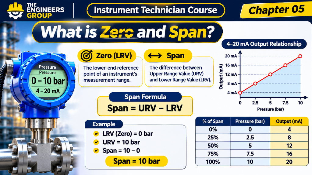
Span is the difference between the Upper Range Value (URV) and Lower Range Value (LRV).
Formula:
Span = URV − LRV
Example:
A pressure transmitter has:
- LRV = 0 bar
- URV = 10 bar
Span = 10 − 0
Span = 10 bar.
Another example:
- LRV = 2 bar
- URV = 12 bar
Span = 12 − 2
Span = 10 bar.
Therefore, the measurement span is 10 bar in both examples, even though the ranges are different.
5. What is Span Adjustment?
Span adjustment is the process of correcting the instrument’s output response across its configured measurement range.
For a standard direct-acting 4–20 mA transmitter:
- At LRV, output = 4 mA.
- At URV, output = 20 mA.
Example:
A pressure transmitter is configured for 0–10 bar.
At 0 bar, expected output = 4 mA.
At 10 bar, expected output = 20 mA.
Suppose the actual output at 10 bar is 19.2 mA, while the lower point is correct.
The technician should investigate the transmitter’s span response and perform a span adjustment if necessary and permitted by the manufacturer.
After adjustment, verify both lower and upper points again.
MASTER INDUSTRIAL
INSTRUMENTATION
Build your technical knowledge with our Instrument Technician E-book – English Edition.
Instrument Technician E-book (English Edition)
Learn essential industrial instrumentation concepts, measurement systems, calibration and troubleshooting in one practical guide.
WHAT YOU WILL LEARN:
- Fundamentals of Industrial Instrumentation
- Pressure, Temperature, Flow and Level Measurement
- Sensors, Transmitters and Control Valves
- Instrument Calibration and Troubleshooting
- PLC, SCADA and Industrial Control Systems
- Essential Instrumentation Interview Preparation
SPECIAL OFFER PRICE
Digital eBook – English Edition
Secure online payment • Digital delivery via email
No physical book will be delivered.
Ideal For:
ITI & Diploma Students | B.Tech Graduates | Instrument Technicians | Junior Engineers
Learn • Practice • Improve Your Engineering Skills
THE ENGINEERS GROUP
6. Difference Between Zero Adjustment and Span Adjustment
| Zero Adjustment | Span Adjustment |
|---|---|
| Corrects the lower-range response | Corrects the measurement interval or sensitivity |
| Checked at LRV | Checked across the configured span, especially at URV |
| Establishes the lower-end output | Establishes the upper-end response relative to the lower point |
| Normally associated with 4 mA for a standard 4–20 mA transmitter | Normally associated with 20 mA at URV |
Remember:
Zero adjustment = Lower-range correction.
Span adjustment = Measurement-span correction.
A change in zero may affect the upper-point error, and a span adjustment may affect the relationship across the range. Therefore, both points must be rechecked after adjustment.
7. What is Calibration?
Calibration is the process of comparing an instrument’s measurement response with a known reference standard under specified conditions.
In simple words, calibration tells us how closely an instrument measures compared with a reliable reference.
During calibration, a technician applies known input values and records the corresponding instrument output.
Example:
A pressure transmitter has a configured range of 0–10 bar and a standard 4–20 mA output.
The technician applies reference pressure using a calibrated pressure source and checks the transmitter’s current output.
| Applied Pressure | Expected Output |
|---|---|
| 0 bar | 4 mA |
| 2.5 bar | 8 mA |
| 5 bar | 12 mA |
| 7.5 bar | 16 mA |
| 10 bar | 20 mA |
If the measured outputs differ from the expected values, the technician records the error and compares it with the permitted tolerance.
Important: Calibration does not automatically mean adjustment. Calibration establishes the measurement relationship and error. Adjustment is performed separately when necessary.
8. Difference Between Calibration and Adjustment
| Calibration | Adjustment |
|---|---|
| Compares the instrument with a reference standard | Changes the instrument response |
| Identifies measurement error | Corrects the response when necessary |
| Can be performed without changing settings | Changes zero, span or configuration |
| Produces calibration results | Aims to bring performance within specified limits |
A proper calibration record should distinguish between as-found and as-left results.
- As-found: Instrument performance before adjustment.
- As-left: Instrument performance after adjustment, if adjustment was performed.
These records are important for maintenance history and quality documentation.
9. What is an Instrument Calibration Standard?
A calibration standard is a reference instrument or device used to provide a known and reliable measurement value.
Examples include:
| Instrument Under Test | Common Calibration Standard |
|---|---|
| Pressure Transmitter | Pressure Calibrator |
| Temperature Transmitter | Temperature Calibrator |
| RTD | Resistance Simulator |
| Thermocouple Transmitter | Thermocouple Simulator |
| Flow Transmitter | Flow Calibration Rig |
| Electrical Signal Transmitter | Loop Calibrator or Precision Multimeter |
The reference standard should have suitable accuracy, a valid calibration status and appropriate measurement range for the task.
10. Types of Calibration
Different instruments require different calibration methods.
10.1 Pressure Transmitter Calibration
A calibrated pressure source applies known pressure to the transmitter.
The technician checks whether the output current corresponds to the applied pressure.
Common equipment:
- Pressure calibrator
- Hand pressure pump
- Reference pressure gauge
- Digital multimeter or loop calibrator
10.2 Temperature Transmitter Calibration
A known temperature or simulated sensor signal is applied to the temperature transmitter.
The technician checks the corresponding output.
Common equipment:
- Temperature calibrator
- RTD simulator
- Thermocouple simulator
- Dry block calibrator
10.3 Differential Pressure Transmitter Calibration
A known differential pressure is applied across the high-pressure and low-pressure ports.
The technician checks the output signal against the configured range.
Common equipment:
- DP pressure calibrator
- Differential pressure source
- Manifold and suitable fittings
- Loop calibrator
10.4 Level Transmitter Calibration
A level transmitter can be checked using a known liquid head, a suitable pressure source or an approved simulation method, depending on the transmitter type and installation.
10.5 Loop Calibration
Loop calibration verifies the complete measurement signal path, which may include:
- Field transmitter
- Field wiring
- Junction box
- Marshalling cabinet
- PLC or DCS analogue input
- Engineering-unit display
It helps identify errors that may not be visible when testing only the transmitter.
💬 NEED GUIDANCE IN INSTRUMENTATION?
Contact THE ENGINEERS GROUP for eBook details, course information and learning support.
MESSAGE US ON WHATSAPP11. Practical Example – 4–20 mA Transmitter Calibration
Consider a pressure transmitter installed in an industrial pipeline.
Transmitter Details:
- Instrument Type = Pressure Transmitter
- LRV = 0 bar
- URV = 10 bar
- Span = 10 bar
- Output Signal = 4–20 mA
Step 1: Calculate the span.
Span = URV − LRV
Span = 10 − 0
Span = 10 bar.
Step 2: Calculate the output at 50% of span.
50% of 10 bar = 5 bar.
At 50% of span, the output is:
Output = 4 + (0.50 × 16)
Output = 12 mA.
Step 3: Calculate the output at 75% of span.
75% of 10 bar = 7.5 bar.
Output = 4 + (0.75 × 16)
Output = 16 mA.
Expected Calibration Results:
| Calibration Point | Applied Pressure | Expected Output |
|---|---|---|
| 0% | 0 bar | 4 mA |
| 25% | 2.5 bar | 8 mA |
| 50% | 5 bar | 12 mA |
| 75% | 7.5 bar | 16 mA |
| 100% | 10 bar | 20 mA |
These points are used to check the transmitter’s response across its configured range.
12. Step-by-Step Practical Pressure Transmitter Calibration Procedure
The following is a general calibration procedure. Always follow the plant’s approved work permit, isolation procedure, instrument manual and safety requirements.
Step 1: Check the Instrument Datasheet
Verify:
- Instrument tag number
- Instrument type
- Measuring range
- LRV and URV
- Output signal
- Accuracy specification
- Calibration tolerance
Step 2: Arrange Calibration Equipment
Select suitable equipment:
- Calibrated pressure calibrator
- Hand pressure pump
- Loop calibrator or digital multimeter
- Correct pressure fittings and tubing
- Suitable electrical test leads
Check that the reference equipment has valid calibration status.
Step 3: Obtain Permission and Isolate the Instrument
Before starting work:
- Obtain the required work permit.
- Inform the control room.
- Follow the approved process isolation procedure.
- Depressurize and verify zero energy where required.
- Follow electrical isolation requirements.
- Apply lockout/tagout where applicable.
Never disconnect a pressurized instrument.
Step 4: Connect the Calibration Equipment
Connect the pressure source to the transmitter’s pressure port using suitable fittings.
Connect the loop calibrator or measuring device to the output circuit according to the approved wiring diagram.
Check polarity and electrical configuration.
Step 5: Record As-Found Readings
Apply the lower-range input and record the output.
Then apply the remaining calibration points in sequence.
For a 0–10 bar transmitter, typical points are:
- 0 bar
- 2.5 bar
- 5 bar
- 7.5 bar
- 10 bar
Record actual readings before making adjustments.
Step 6: Compare Actual and Expected Output
Compare the measured current with the expected current at every point.
Identify whether the error is within the manufacturer’s or plant’s acceptance tolerance.
Step 7: Perform Adjustment if Required
If the instrument fails the acceptance criteria, investigate the cause.
Perform zero and/or span adjustment only when necessary and permitted by the manufacturer’s instructions.
Step 8: Perform As-Left Verification
Repeat the calibration points after adjustment.
Record the final readings and verify that the instrument meets the required tolerance.
Step 9: Restore the Instrument
After successful calibration:
- Restore the original connections.
- Close process isolation points as per procedure.
- Remove test equipment safely.
- Check for leakage where applicable.
- Restore the instrument to service.
- Confirm the correct process reading with the control room.
Step 10: Complete Calibration Documentation
Record:
- Instrument tag number
- Date of calibration
- Technician details
- Reference equipment identification
- As-found readings
- Adjustments performed
- As-left readings
- Acceptance status
- Next calibration due date, as specified by the maintenance system
13. What is Calibration Error?
Calibration error is the difference between the instrument’s measured output and the expected reference output at a specified input.
Formula:
Error = Measured Output − Expected Output
Example:
Expected output = 12 mA
Measured output = 12.2 mA
Error = 12.2 − 12
Error = +0.2 mA.
The positive sign indicates that the instrument output is higher than expected.
Percentage of Output Span Error:
Percentage Error = (Absolute Error / Output Span) × 100
For a 4–20 mA transmitter:
Output Span = 20 − 4 = 16 mA.
Percentage Error = (0.2 / 16) × 100
Percentage Error = 1.25% of output span.
Always identify the basis of the accuracy specification: percentage of span, percentage of reading, percentage of full scale or another manufacturer-defined specification.
14. What is Hysteresis in Calibration?
Hysteresis is the difference in an instrument’s output at the same input value when that input is approached from increasing and decreasing directions.
Example:
A pressure transmitter is tested at 5 bar.
During the increasing-pressure test, output = 12.1 mA.
During the decreasing-pressure test, output = 11.9 mA.
Hysteresis difference = 12.1 − 11.9
Hysteresis difference = 0.2 mA.
Hysteresis can be caused by mechanical friction, backlash or other instrument characteristics.
15. What is Linearity Error?
Linearity error is the deviation of an instrument’s actual input-output relationship from its specified straight-line relationship.
For a linear 0–10 bar pressure transmitter with a 4–20 mA output, the ideal output at 5 bar is 12 mA.
If the actual output is 12.3 mA, the deviation from the ideal value is +0.3 mA.
The error must be evaluated according to the manufacturer’s specification and the applicable acceptance criteria.
16. Common Problems During Transmitter Calibration
Problem 1: Output is not 4 mA at LRV.
Possible causes:
- Incorrect zero configuration
- Incorrect applied reference pressure
- Wiring or loop measurement issue
- Transmitter fault
Problem 2: Output is not 20 mA at URV.
Possible causes:
- Incorrect span configuration
- Incorrect reference pressure
- Sensor or transmitter problem
- Incorrect range settings
Problem 3: Output fluctuates during calibration.
Possible causes:
- Unstable pressure source
- Loose electrical connections
- Pressure leakage
- Electrical interference
- Unstable process or test conditions
Problem 4: Transmitter reading differs from the reference standard.
Possible causes:
- Calibration drift
- Incorrect configuration
- Reference equipment error
- Installation-related problems
- Sensor damage
Problem 5: Output is correct at zero but incorrect at higher points.
Possible causes:
- Span error
- Nonlinearity
- Incorrect URV configuration
- Sensor performance issue
Do not immediately adjust the transmitter. First confirm the reference source, measurement setup, configuration and instrument condition.
17. Difference Between Zero, Span and Calibration
| Parameter | Meaning |
|---|---|
| Zero | Lower-end reference point of the configured range |
| Zero Adjustment | Correction of the lower-range response |
| Span | Difference between URV and LRV |
| Span Adjustment | Correction of measurement response across the range |
| Calibration | Comparison against a known reference standard |
| As-found | Results recorded before adjustment |
| As-left | Results recorded after adjustment |
18. Why Is Instrument Calibration Important?
1. Measurement Reliability
Calibration helps determine whether an instrument provides reliable measurement results.
2. Process Control
Correct transmitter measurements help PLC and DCS systems maintain the required process conditions.
3. Plant Safety
Reliable measurements help operators monitor pressure, temperature, flow and level conditions.
4. Product Quality
Accurate measurements help maintain consistent manufacturing processes.
5. Maintenance Planning
Calibration records help identify instrument drift and determine maintenance requirements.
6. Compliance and Documentation
Calibration certificates and records provide evidence of measurement performance and traceability.
19. Common Mistakes Made by Instrument Technicians
- Confusing zero adjustment with calibration.
- Confusing span with URV.
- Adjusting a transmitter without recording as-found readings.
- Using an unsuitable or out-of-calibration reference instrument.
- Ignoring the manufacturer’s accuracy specification.
- Performing calibration without proper process isolation.
- Not checking the instrument configuration.
- Forgetting to verify the output at multiple points.
- Not recording as-left results.
- Returning an instrument to service without proper restoration and control-room confirmation.
20. Instrument Technician Interview Questions and Answers
Q1. What is zero in instrumentation?
Answer: Zero is the lower-end reference point of an instrument’s configured measurement range.
Q2. What is zero adjustment?
Answer: Zero adjustment corrects the instrument’s response at its lower range value.
Q3. What is span?
Answer: Span is the difference between URV and LRV.
Q4. What is span adjustment?
Answer: Span adjustment corrects the instrument’s measurement response across its configured range.
Q5. What is calibration?
Answer: Calibration is the comparison of an instrument’s measurement response with a known reference standard under specified conditions.
Q6. What is the difference between calibration and adjustment?
Answer: Calibration identifies the measurement relationship and error, while adjustment changes the instrument response to correct it.
Q7. What is the output at LRV for a standard direct-acting 4–20 mA transmitter?
Answer: 4 mA.
Q8. What is the output at URV for a standard direct-acting 4–20 mA transmitter?
Answer: 20 mA.
Q9. What is an as-found reading?
Answer: It is the instrument reading recorded before any adjustment is performed.
Q10. What is an as-left reading?
Answer: It is the instrument reading recorded after adjustment and final verification.
Q11. Which equipment is used for pressure transmitter calibration?
Answer: A calibrated pressure source or pressure calibrator, suitable pressure pump and a loop calibrator or multimeter.
Q12. What is hysteresis?
Answer: Hysteresis is the difference in output at the same input when approached from increasing and decreasing directions.
Q13. What is linearity error?
Answer: It is the deviation of the actual input-output relationship from the specified straight-line relationship.
Q14. Why is calibration important?
Answer: Calibration helps verify measurement performance, detect errors and maintain reliable industrial process measurements.
Q15. Should a transmitter always be adjusted during calibration?
Answer: No. Adjustment is required only when the calibration results and acceptance criteria indicate that correction is necessary.
21. Multiple Choice Questions (MCQs)
Q1. What is zero in instrumentation?
A. Highest measurement value
B. Lower-end reference point
C. Total measurement span
D. Maximum output current
Correct Answer: B. Lower-end reference point
Q2. What is the formula for span?
A. LRV + URV
B. URV − LRV
C. URV × LRV
D. LRV / URV
Correct Answer: B. URV − LRV
Q3. What is the standard output at LRV for a direct-acting 4–20 mA transmitter?
A. 0 mA
B. 4 mA
C. 12 mA
D. 20 mA
Correct Answer: B. 4 mA
Q4. What is the standard output at URV?
A. 4 mA
B. 8 mA
C. 12 mA
D. 20 mA
Correct Answer: D. 20 mA
Q5. What is calibration?
A. Replacing an instrument
B. Comparing an instrument with a reference standard
C. Increasing the supply voltage
D. Changing the instrument tag
Correct Answer: B. Comparing an instrument with a reference standard
Q6. What is an as-found reading?
A. Reading after adjustment
B. Reading before adjustment
C. Maximum reading
D. Minimum reading
Correct Answer: B. Reading before adjustment
Q7. What is an as-left reading?
A. Reading after adjustment and verification
B. Reading before calibration
C. Reference pressure only
D. Instrument range
Correct Answer: A. Reading after adjustment and verification
Q8. Which equipment is commonly used for pressure transmitter calibration?
A. Tachometer
B. Pressure calibrator
C. Lux meter
D. Clamp meter only
Correct Answer: B. Pressure calibrator
Q9. Hysteresis is related to:
A. Difference between increasing and decreasing input responses
B. Instrument range only
C. Supply frequency
D. Output wiring colour
Correct Answer: A. Difference between increasing and decreasing input responses
Q10. Should a transmitter always be adjusted during calibration?
A. Yes, every time
B. No, only when required
C. Only at 50%
D. Only when output is 4 mA
Correct Answer: B. No, only when required
Q11. A transmitter has LRV = 0 bar and URV = 10 bar. What is its span?
A. 5 bar
B. 10 bar
C. 20 bar
D. 0 bar
Correct Answer: B. 10 bar
Q12. What is the ideal output at 50% of span for a standard 4–20 mA transmitter?
A. 4 mA
B. 8 mA
C. 12 mA
D. 20 mA
Correct Answer: C. 12 mA
Q13. What should be recorded before making a calibration adjustment?
A. As-found readings
B. Only the instrument serial number
C. Only the final output
D. No readings are required
Correct Answer: A. As-found readings
Q14. Which instrument is commonly used to simulate an RTD signal?
A. RTD simulator
B. Pressure gauge
C. Flow switch
D. Tachometer
Correct Answer: A. RTD simulator
Q15. What should be done before disconnecting a pressurized transmitter?
A. Immediately loosen the fitting
B. Increase the pressure
C. Follow approved isolation and depressurization procedures
D. Remove the electrical cable only
Correct Answer: C. Follow approved isolation and depressurization procedures
22. Chapter Summary
In this chapter, we learned the fundamentals of zero, span and instrument calibration.
Key points:
- Zero is the lower-end reference point of a configured measurement range.
- Zero adjustment corrects the lower-range response.
- Span is calculated using URV − LRV.
- Span adjustment corrects the instrument’s measurement response across its range.
- Calibration compares instrument performance with a known reference standard.
- Calibration and adjustment are different activities.
- As-found readings are recorded before adjustment.
- As-left readings are recorded after adjustment and verification.
- Pressure, temperature, flow and level instruments require suitable calibration methods and reference equipment.
- Safety, isolation, calibration records and final verification are essential during industrial calibration work.
Understanding these concepts helps Instrument Technicians perform calibration, commissioning, maintenance and troubleshooting more effectively.
23. What Is Next?
CHAPTER 06: Static and Dynamic Characteristics of Instruments
In the next chapter, we will learn:
- What are Static Characteristics?
- What are Dynamic Characteristics?
- Sensitivity and Linearity
- Hysteresis and Repeatability
- Dead Band and Drift
- Response Time and Time Constant
- Instrument Performance in Industrial Applications
- Interview Questions and MCQs
Continue learning with THE ENGINEERS GROUP – Your Free Industrial Instrumentation Learning Platform.
Learn. Practice. Improve. Grow.
CONNECT WITH THE ENGINEERS GROUP
Learn. Practice. Improve. Grow.
📘 BUY INSTRUMENTATION E-BOOK 💬 CONTACT US ON WHATSAPP ▶️ SUBSCRIBE ON YOUTUBE f FOLLOW US ON FACEBOOKTHE ENGINEERS GROUP
Free Engineering Education for Everyone