
PLC Programming Course – Chapter 05: PLC Programming Languages Explained
PLC Programming Course – Chapter 05
Table of Contents
- Introduction to PLC Programming Languages
- What Are PLC Programming Languages?
- IEC 61131-3 Standard
- Types of PLC Programming Languages
- Ladder Diagram (LD)
- Function Block Diagram (FBD)
- Structured Text (ST)
- Sequential Function Chart (SFC)
- Instruction List (IL) – Legacy Language
- Comparison of PLC Programming Languages
- PLC Programming Languages Practical Examples
- Motor Start and Stop Using Ladder Logic
- Timer and Counter Programming
- Analog Signal Processing Using Structured Text
- How to Select the Right PLC Programming Language
- Popular PLC Programming Software
- Common PLC Programming Mistakes
- Best Practices for PLC Programming
- PLC Programming Interview Questions and Answers
- PLC Programming MCQs
- Chapter Summary
- What You Will Learn in Chapter 06
1. Introduction to PLC Programming Languages
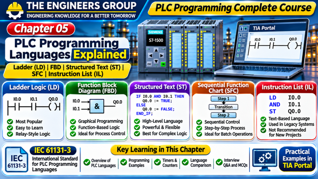
PLC Programming Languages are used to develop control programs that operate industrial machines, equipment, and automated processes.
A Programmable Logic Controller (PLC) receives signals from field devices, executes a user-developed control program, and operates output devices according to the programmed logic.
Different programming languages are available to develop PLC applications. Each language has its own structure, advantages, and applications.
For example:
- Ladder Diagram (LD) is widely used for relay-based logic and machine control.
- Function Block Diagram (FBD) is useful for graphical function-based programming.
- Structured Text (ST) is suitable for mathematical operations and complex logic.
- Sequential Function Chart (SFC) is useful for step-by-step process control.
Understanding these programming languages helps technicians and engineers develop, maintain, troubleshoot, and modify industrial automation systems.
2. What Are PLC Programming Languages?
PLC Programming Languages are standardized or manufacturer-supported methods used to write instructions for a Programmable Logic Controller.
These languages define how the PLC should respond to input conditions and control output devices.
For example, consider a simple motor control application.
Input Devices:
- Start Push Button
- Stop Push Button
- Overload Relay Feedback
Output Device:
- Motor Contactor
The programmer develops a control program that checks the input conditions and operates the motor contactor accordingly.
The PLC programming language provides the instructions required to implement this control logic.
3. IEC 61131-3 Standard
IEC 61131-3 is an international standard that defines programming language concepts and structures for programmable controllers.
It provides a common framework for developing PLC control programs.
The standard includes several programming language approaches.
The commonly recognized languages include:
- Ladder Diagram (LD)
- Function Block Diagram (FBD)
- Structured Text (ST)
- Sequential Function Chart (SFC)
Instruction List (IL) is a legacy textual language associated with earlier editions of IEC 61131-3. It was deprecated in the third edition and is not recommended for new projects.
Importance of IEC 61131-3
- Provides standardized programming concepts.
- Supports structured program development.
- Improves program organization.
- Helps engineers understand different programming approaches.
- Supports reusable software elements.
- Encourages consistent programming practices.
Note: The availability and implementation of programming languages depend on the PLC manufacturer, controller family, engineering software, and firmware version.
4. Types of PLC Programming Languages
PLC programming approaches can be divided into graphical and textual languages.
Graphical Languages
Graphical languages represent control logic using symbols, blocks, and diagrams.
Examples:
- Ladder Diagram (LD)
- Function Block Diagram (FBD)
- Sequential Function Chart (SFC)
Textual Languages
Textual languages use written instructions and programming statements.
Examples:
- Structured Text (ST)
- Instruction List (IL) – legacy language
Each language can be useful for different types of industrial applications.
💬 NEED GUIDANCE IN PLC?
Contact THE ENGINEERS GROUP for eBook details, course information and learning support.
MESSAGE US ON WHATSAPP5. Ladder Diagram (LD)
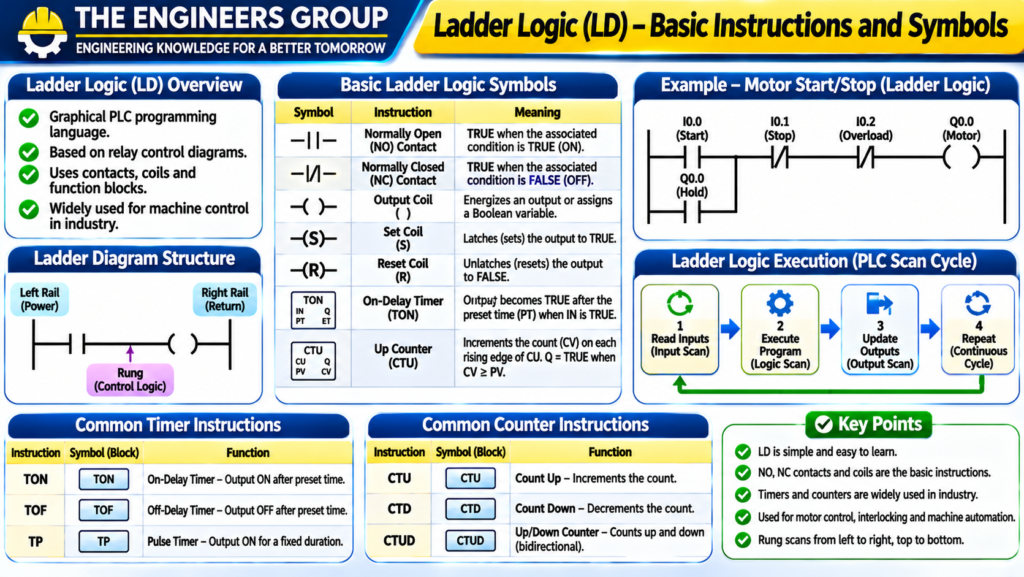
Ladder Diagram, commonly called Ladder Logic, is one of the most widely used PLC programming languages in industrial automation.
It is based on the electrical relay control diagrams traditionally used in industrial control panels.
Ladder Logic represents control operations using horizontal rungs between two vertical power rails.
Each rung contains contacts, coils, and other supported instructions.
Basic Ladder Logic Components
5.1 Normally Open Contact (NO)
A normally open contact instruction is TRUE when its associated Boolean condition is TRUE.
It is commonly used to represent a push button, sensor, or internal Boolean variable.
5.2 Normally Closed Contact (NC)
A normally closed contact instruction is TRUE when its associated Boolean condition is FALSE.
It is commonly used in interlocking and permissive logic.
Important: An NC ladder instruction does not automatically mean the physical field contact is wired as normally closed. The physical device and the programmed instruction are separate concepts.
5.3 Output Coil
An output coil represents an assignment to a Boolean output or variable.
When the rung conditions are TRUE, the coil is energized or assigned TRUE, depending on the PLC platform and instruction behavior.
5.4 Timer Instruction
A timer instruction is used to create time-based control operations.
Common timer types include:
- TON – On-Delay Timer
- TOF – Off-Delay Timer
- TP – Pulse Timer
5.5 Counter Instruction
Counter instructions are used to count events or pulses.
Common types include:
- CTU – Count Up
- CTD – Count Down
- CTUD – Count Up/Down
Advantages of Ladder Logic
- Easy to understand for electrical technicians.
- Similar to traditional relay diagrams.
- Widely supported by industrial PLC platforms.
- Useful for machine control.
- Convenient for online monitoring and troubleshooting.
Applications of Ladder Logic
- Motor Start/Stop Control
- Conveyor Systems
- Pump Control
- Interlocking Logic
- Alarm Systems
- Machine Automation
6. Function Block Diagram (FBD)
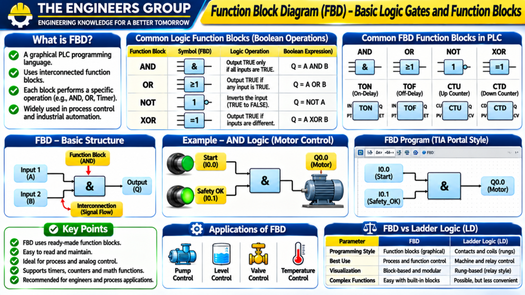
Function Block Diagram is a graphical PLC programming language in which control logic is represented using interconnected function blocks.
Each block performs a specific operation.
Examples include:
- AND
- OR
- NOT
- Timer
- Counter
- Comparator
- Arithmetic Function
- PID Controller
The blocks are connected through input and output signals.
Working Principle
- Input signals are connected to function block inputs.
- The block performs its programmed operation.
- The result is transferred through its output.
- The output can be connected to another block or assigned to a variable.
Example: AND Logic
Suppose a motor should start only when both Start and Safety Permissive conditions are TRUE.
Inputs:
- Start_Command
- Safety_OK
Logic:
Motor_Run = Start_Command AND Safety_OK
The AND function block produces TRUE only when both inputs are TRUE.
Advantages of FBD
- Graphical programming structure.
- Easy visualization of signal flow.
- Useful for process control.
- Supports reusable function blocks.
- Convenient for mathematical and control functions.
Applications of FBD
- PID Control
- Process Automation
- Temperature Control
- Flow Control
- Level Control
- Signal Processing
7. Structured Text (ST)
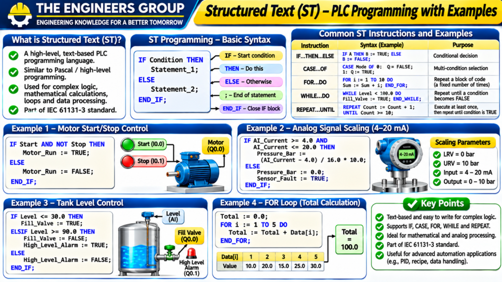
Structured Text is a high-level textual PLC programming language.
It uses programming statements, variables, conditions, loops, and mathematical expressions.
Its syntax is similar to conventional high-level programming languages.
Structured Text is especially useful for complex logic, mathematical calculations, data handling, and advanced control applications.
Common Structured Text Statements
IF Statement
Used to execute logic based on a condition.
Example:
IF Start_Command AND Safety_OK THEN
    Motor_Run := TRUE;
ELSE
    Motor_Run := FALSE;
END_IF;
CASE Statement
Used when different actions are required for different operating conditions.
Example:
CASE Machine_Mode OF

    0:
        Motor_Run := FALSE;

    1:
        Motor_Run := TRUE;

    2:
        Motor_Run := FALSE;
        Alarm := TRUE;

END_CASE;
FOR Loop
Used to repeat instructions over a defined range.
Example:
FOR Index := 1 TO 5 DO
    Total := Total + Values[Index];
END_FOR;
The example assumes that the variables and array are declared and initialized appropriately.
Advantages of Structured Text
- Suitable for complex mathematical operations.
- Supports structured programming.
- Useful for data processing.
- Supports conditions and loops.
- Can reduce repetitive logic.
- Useful for advanced automation applications.
Applications of Structured Text
- Mathematical Calculations
- Data Processing
- Recipe Management
- Advanced Machine Control
- Array Operations
- Complex Process Logic
8. Sequential Function Chart (SFC)
Sequential Function Chart is a graphical programming method used to represent sequential machine and process operations.
It organizes a control sequence into steps and transitions.
A Step represents a particular stage of operation.
A Transition defines the condition required to move from one step to another.
Main Elements of SFC
8.1 Step
A step represents a stage in a machine or process sequence.
Example:
- Step 1: Wait for Start
- Step 2: Start Motor
- Step 3: Open Valve
- Step 4: Complete Operation
8.2 Transition
A transition determines when the sequence can move to the next step.
For example, when a sensor detects the required position, the transition condition becomes TRUE.
8.3 Action
An action defines the operation associated with a step.
Examples:
- Start Motor
- Open Valve
- Activate Alarm
- Start Timer
Practical Example: Automatic Tank Filling
A tank filling sequence can be organized into the following steps:
Step 1: Wait for Start Command.
Step 2: Check Low-Level Condition.
Step 3: Start Filling Pump.
Step 4: Monitor Tank Level.
Step 5: Stop Pump at High Level.
Step 6: Activate Complete Indication.
Advantages of SFC
- Easy visualization of sequences.
- Suitable for multi-step operations.
- Simplifies complex machine sequences.
- Improves program organization.
- Useful for troubleshooting sequence operations.
Applications of SFC
- Batch Processing
- Packaging Machines
- Assembly Lines
- Automatic Filling Systems
- Material Handling
- Sequential Machine Control
9. Instruction List (IL) – Legacy Language
Instruction List was a low-level textual PLC programming language included in earlier IEC 61131-3 editions.
It used short instruction mnemonics to represent logical operations.
Example of legacy-style IL:
LD    Start_Command
AND   Safety_OK
ST    Motor_Run
This represents loading the Start_Command condition, combining it with Safety_OK, and storing the result in Motor_Run.
Instruction List was used in some older PLC programming systems.
However, it was deprecated in the third edition of IEC 61131-3.
It is important to understand IL when maintaining legacy PLC programs, but it should not be selected for new projects unless a specific legacy platform requires it.
10. Comparison of PLC Programming Languages
| Language | Type | Main Application |
|---|---|---|
| Ladder Diagram (LD) | Graphical | Machine and relay logic |
| Function Block Diagram (FBD) | Graphical | Process and function-based control |
| Structured Text (ST) | Textual | Complex logic and calculations |
| Sequential Function Chart (SFC) | Graphical | Sequential process control |
| Instruction List (IL) | Textual, legacy | Older PLC programs |
Ladder Logic vs FBD
| Parameter | Ladder Logic | FBD |
|---|---|---|
| Programming Style | Relay-style diagram | Function blocks |
| Structure | Rungs | Connected blocks |
| Best Use | Machine control | Process and function logic |
| Monitoring | Contact and coil status | Block signal status |
| Familiarity | Electrical technicians | Control and automation engineers |
Ladder Logic vs Structured Text
| Parameter | Ladder Logic | Structured Text |
|---|---|---|
| Type | Graphical | Textual |
| Readability | Electrical diagram style | Programming statement style |
| Complex Calculations | Can be less convenient | Usually more convenient |
| Troubleshooting | Rung monitoring | Variable and statement monitoring |
| Application | Discrete control | Advanced logic and data processing |
11. PLC Programming Languages Practical Examples
Let’s understand how different programming languages can implement similar control operations.
Example 1: Motor Start Condition
Requirement:
The motor should run only when the Start Command and Safety Permissive are TRUE.
Boolean Logic:
Motor_Run = Start_Command AND Safety_OK
This logic can be implemented using:
- Ladder Diagram: Two series contacts and an output coil.
- FBD: An AND block connected to the motor run variable.
- ST: An IF statement or Boolean assignment.
Example 2: Tank High-Level Alarm
Requirement:
Activate a high-level alarm when tank level reaches or exceeds 90%.
Structured Text example:
IF Tank_Level >= 90.0 THEN
    High_Level_Alarm := TRUE;
ELSE
    High_Level_Alarm := FALSE;
END_IF;
The variable Tank_Level must be correctly scaled and declared as a suitable numeric data type.
Example 3: Conveyor Sequence
Requirement:
- Wait for Start Command.
- Start Conveyor Motor.
- Detect Product.
- Stop Conveyor when the required count is reached.
- Activate Completion Alarm.
This sequence can be represented using SFC steps and transitions.
12. Motor Start and Stop Using Ladder Logic
Let’s understand a basic motor start/stop control application.
Required Inputs
| Input | Description |
|---|---|
| I0.0 | Start Push Button |
| I0.1 | Stop Circuit Healthy |
| I0.2 | Overload Healthy |
Required Output
| Output | Description |
|---|---|
| Q0.0 | Motor Contactor Command |
Basic Control Logic
The motor should run when:
- Start Command is received.
- Stop Circuit is healthy.
- Overload is healthy.
A practical motor latch circuit can use a parallel holding contact around the Start contact, with Stop and Overload permissives in series.
Simplified Boolean expression:
Motor_Run = (Start_Command OR Motor_Run) AND Stop_OK AND Overload_OK
The exact physical input logic depends on how the field contacts are wired and how the PLC inputs are configured.
Safety Note: This is a basic control example, not a safety-rated emergency stop design. Use appropriate safety relays or safety PLCs and validated safety circuits where required.
13. Timer and Counter Programming
Timers and counters are commonly used in PLC automation.
13.1 On-Delay Timer (TON)
A TON timer delays its output until its input condition remains TRUE for the configured preset time.
Example:
A conveyor motor should start after a 5-second delay.
Typical sequence:
- Start command becomes TRUE.
- TON timer begins counting.
- After the preset time, the timer output becomes TRUE.
- The motor run command is enabled if all other permissives are healthy.
13.2 Off-Delay Timer (TOF)
A TOF timer keeps its output TRUE for a configured period after the input condition becomes FALSE.
Example:
A cooling fan continues operating for 30 seconds after a machine stops.
13.3 Pulse Timer (TP)
A pulse timer generates an output pulse for a configured duration after a triggering condition.
Example:
A pneumatic valve receives a timed activation pulse.
13.4 Counter (CTU)
An Up Counter increments its count when the required counting event occurs.
Example:
A conveyor system counts products using a proximity sensor.
When the counter reaches the preset value, the PLC can stop the conveyor or activate a batch-complete indication.
14. Analog Signal Processing Using Structured Text
Structured Text can be used to convert raw analog values into engineering units.
Consider a pressure transmitter with:
- LRV = 0 bar
- URV = 10 bar
- Signal = 4–20 mA
The pressure scaling formula is:
Pressure = [(Current − 4) / 16] × 10
Structured Text example:
IF Transmitter_Current >= 4.0
   AND Transmitter_Current <= 20.0 THEN

    Pressure_Bar :=
        ((Transmitter_Current - 4.0) / 16.0) * 10.0;

ELSE
    Transmitter_Fault := TRUE;
END_IF;
This is a simplified example. A production program should also handle under-range and over-range conditions, sensor diagnostics, data types, and fault recovery.
15. How to Select the Right PLC Programming Language
Selecting the right programming language depends on the application, programming environment, maintenance requirements, and engineering team experience.
Consider the Following Factors
1. Application Type
For basic machine control, Ladder Logic may be a suitable choice.
For complex calculations, Structured Text may be more convenient.
For sequential operations, SFC can provide a clear process structure.
2. Maintenance Requirements
Choose a programming approach that technicians and engineers can understand and maintain.
3. PLC Manufacturer Support
Check which programming languages are supported by the selected PLC and software version.
4. Program Complexity
For large and complex applications, structured programming and reusable function blocks can improve organization.
5. Team Knowledge
Consider the experience and training level of the engineers and maintenance technicians.
16. Popular PLC Programming Software
Different PLC manufacturers provide engineering software for developing, testing, and maintaining PLC programs.
| Manufacturer | PLC Programming Software |
|---|---|
| Siemens | TIA Portal |
| Rockwell Automation | Studio 5000 Logix Designer |
| Schneider Electric | EcoStruxure Control Expert |
| Mitsubishi Electric | GX Works |
| Omron | Sysmac Studio |
| ABB | Automation Builder |
The supported programming languages and features vary by controller family and software version.
Siemens TIA Portal
TIA Portal is used to configure and program supported Siemens PLCs such as S7-1200 and S7-1500.
It supports programming approaches such as LAD, FBD, and SCL (Siemens’ implementation of Structured Text), depending on the controller and software configuration.
Rockwell Studio 5000
Studio 5000 Logix Designer is used to configure and program supported Allen-Bradley Logix controllers.
It provides programming environments such as Ladder Diagram, Function Block Diagram, and Structured Text, depending on the controller and license.
17. Common PLC Programming Mistakes
Incorrect PLC programming can cause machine stoppages, unexpected operation, and process disturbances.
Common mistakes include:
- Incorrect input and output addressing.
- Missing interlocks and permissives.
- Incorrect timer preset values.
- Incorrect counter reset logic.
- Incorrect analog scaling.
- Missing fault-handling logic.
- Poor variable naming.
- Duplicate or conflicting output assignments.
- Inadequate program documentation.
- Insufficient testing before commissioning.
Troubleshooting Tips
- Monitor input and output status online.
- Check PLC diagnostic messages.
- Verify hardware configuration.
- Review timer and counter values.
- Check analog signal scaling.
- Verify interlocks and operating conditions.
- Test the program in a safe environment before production use.
18. Best Practices for PLC Programming
Professional PLC programs should be easy to understand, maintain, and troubleshoot.
Follow these practices:
- Use meaningful variable names.
- Divide large programs into logical sections.
- Use reusable function blocks where appropriate.
- Add comments and documentation.
- Use consistent programming standards.
- Implement suitable fault-handling logic.
- Verify I/O addressing.
- Test all operating conditions.
- Maintain backups and version control.
- Follow plant safety procedures and approved change-management processes.
19. PLC Programming Interview Questions and Answers
Q1. What are PLC Programming Languages?
PLC Programming Languages are methods used to write control instructions for programmable logic controllers.
Q2. What is IEC 61131-3?
It is an international standard that defines programming language concepts and structures for programmable controllers.
Q3. What is Ladder Logic?
Ladder Logic is a graphical PLC programming language based on relay control diagrams.
Q4. What is FBD?
Function Block Diagram is a graphical programming language that represents logic through interconnected function blocks.
Q5. What is Structured Text?
Structured Text is a high-level textual PLC programming language used for calculations, conditions, loops, and complex logic.
Q6. What is SFC?
Sequential Function Chart is a graphical programming method used to organize sequential operations into steps and transitions.
Q7. Which PLC language is similar to electrical relay diagrams?
Ladder Diagram.
Q8. Which PLC language is suitable for complex mathematical calculations?
Structured Text is generally convenient for complex calculations.
Q9. What is a function block?
A function block is a reusable program element that performs a defined operation and can maintain internal state.
Q10. What is a TON timer?
TON is an On-Delay Timer that delays its output after its input becomes TRUE.
Q11. What is a TOF timer?
TOF is an Off-Delay Timer that delays the change of its output after its input becomes FALSE.
Q12. What is a CTU counter?
CTU is an Up Counter that increments its count when a valid counting event occurs.
Q13. What is the purpose of SFC?
SFC organizes sequential machine and process operations into steps and transitions.
Q14. What is Structured Text used for?
It is used for calculations, data handling, conditions, loops, and complex control logic.
Q15. What is the difference between LD and FBD?
LD uses relay-style contacts and coils, while FBD uses interconnected function blocks.
Q16. What is the difference between graphical and textual PLC languages?
Graphical languages represent logic through diagrams and symbols, while textual languages use written programming statements.
Q17. What is TIA Portal?
TIA Portal is Siemens engineering software used to configure and program supported automation devices.
Q18. What is Studio 5000?
Studio 5000 Logix Designer is Rockwell Automation software used to configure and program supported Logix controllers.
Q19. Is Instruction List still recommended for new PLC projects?
No. Instruction List is a legacy language that was deprecated in the third edition of IEC 61131-3.
Q20. Which PLC programming language should beginners learn first?
Ladder Logic is often a practical starting point because it is widely used in industrial machine control and resembles relay diagrams.
FREE 100 PLC INTERVIEW Q&A PDF DOWNLOAD
Download your free PLC learning material.
📥 DOWNLOAD FREE PLC PDFTHE ENGINEERS GROUP
\20. PLC Programming MCQs
Q1. Which PLC programming language resembles relay control diagrams?
A. Structured Text
B. Ladder Diagram
C. SFC
D. Instruction List
Correct Answer: B. Ladder Diagram
Q2. What does FBD stand for?
A. Function Block Diagram
B. Field Bus Device
C. Functional Binary Data
D. Field Block Design
Correct Answer: A. Function Block Diagram
Q3. Which language is textual?
A. Ladder Diagram
B. FBD
C. Structured Text
D. SFC
Correct Answer: C. Structured Text
Q4. Which language is suitable for sequential machine operations?
A. SFC
B. Ladder only
C. IL only
D. None
Correct Answer: A. SFC
Q5. Which standard defines PLC programming language concepts?
A. IEC 61131-3
B. IEC 60204 only
C. ISO 9001
D. IEEE 802.3
Correct Answer: A. IEC 61131-3
Q6. What does TON represent?
A. Timer On-Delay
B. Timer Off-Delay
C. Total Output Number
D. Time Operation Network
Correct Answer: A. Timer On-Delay
Q7. What does CTU represent?
A. Counter Timer Up
B. Count Up
C. Control Time Unit
D. Counter Transfer Unit
Correct Answer: B. Count Up
Q8. Which language uses interconnected function blocks?
A. Ladder Diagram
B. FBD
C. Structured Text
D. IL
Correct Answer: B. FBD
Q9. Which language is convenient for loops and mathematical calculations?
A. Structured Text
B. SFC only
C. Ladder only
D. None
Correct Answer: A. Structured Text
Q10. Which PLC programming language is considered legacy and deprecated in the third edition of IEC 61131-3?
A. LD
B. FBD
C. ST
D. IL
Correct Answer: D. IL
Q11. Which software is commonly used for Siemens S7-1200 and S7-1500 programming?
A. TIA Portal
B. AutoCAD
C. Photoshop
D. Excel
Correct Answer: A. TIA Portal
Q12. Which software is used for supported Rockwell Logix controllers?
A. GX Works
B. Studio 5000 Logix Designer
C. TIA Portal
D. Sysmac Studio
Correct Answer: B. Studio 5000 Logix Designer
Q13. What is a transition in SFC?
A. A PLC power supply
B. A condition that controls movement between steps
C. A physical input module
D. A timer reset only
Correct Answer: B. A condition that controls movement between steps
Q14. Which timer keeps its output active for a period after the input becomes FALSE?
A. TON
B. TOF
C. CTU
D. CTD
Correct Answer: B. TOF
Q15. Which programming language is widely used for basic industrial motor control logic?
A. Ladder Diagram
B. HTML
C. CSS
D. SQL
Correct Answer: A. Ladder Diagram
21. Chapter Summary
In this chapter, we learned about PLC Programming Languages and their applications in industrial automation.
We studied Ladder Diagram, Function Block Diagram, Structured Text, Sequential Function Chart, and the legacy Instruction List language.
We also explored the IEC 61131-3 standard, practical programming examples, motor control logic, timers, counters, analog signal processing, programming software, and PLC programming best practices.
Understanding PLC programming languages is essential for developing industrial automation programs and troubleshooting PLC-controlled machines.
22. What You Will Learn in Chapter 06
In the next chapter, we will study:
Ladder Logic Programming – Basic Instructions, Contacts, Coils and Practical Examples
Topics will include:
- Introduction to Ladder Logic
- Normally Open and Normally Closed Contacts
- Output Coils
- Series and Parallel Logic
- AND, OR and NOT Logic
- Latching and Unlatching
- Motor Start/Stop Programming
- Practical Ladder Logic Diagrams
- Troubleshooting Ladder Logic
- Interview Questions and MCQs
Continue learning with THE ENGINEERS GROUP.
THE ENGINEERS GROUP
ENGINEERING KNOWLEDGE FOR A BETTER TOMORROW
Learn. Practice. Grow.
CONNECT WITH THE ENGINEERS GROUP
Learn. Practice. Improve. Grow.
📘 EXPLORE OUR EBOOK 💬 CONTACT US ON WHATSAPP ▶️ SUBSCRIBE ON YOUTUBE FOLLOW US ON FACEBOOKTHE ENGINEERS GROUP
Free Engineering Education for Everyone