
PLC Programming Course – Chapter 04: PLC Input and Output (I/O) System Explained
PLC Programming Course – Chapter 04
Table of Contents
- Introduction to PLC Input and Output System
- What Is a PLC I/O System?
- Basic PLC I/O Architecture
- Types of PLC Input and Output
- Digital Input (DI) Module
- Digital Output (DO) Module
- Analog Input (AI) Module
- Analog Output (AO) Module
- Difference Between Digital and Analog I/O
- PNP and NPN Sensors
- Sinking and Sourcing Concepts
- PLC Digital Input Wiring
- PLC Digital Output Wiring
- PLC Analog Input Wiring
- PLC Analog Output Wiring
- PLC I/O Addressing
- Practical Industrial PLC I/O Example
- Common PLC I/O Problems and Troubleshooting
- Important PLC I/O Terminology
- PLC I/O Interview Questions and Answers
- PLC I/O MCQs
- Chapter Summary
- What You Will Learn in Chapter 05
PLC Input Output System – Digital and Analog I/O Explained
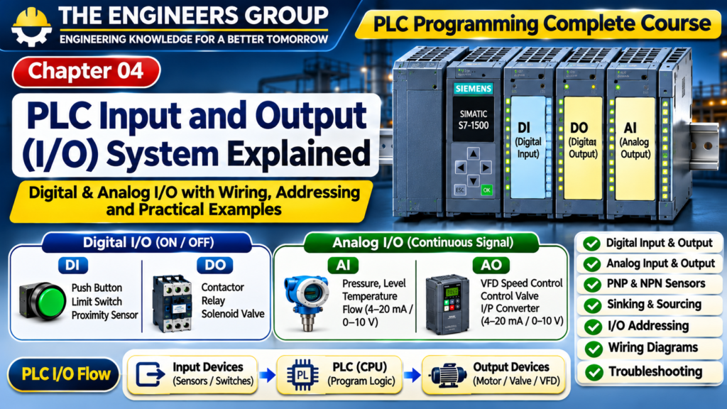
The PLC Input Output system is divided into four main categories: Digital Input (DI), Digital Output (DO), Analog Input (AI), and Analog Output (AO). Each category performs a specific function in industrial automation, from receiving sensor signals to controlling motors, valves, and other field devices.
The PLC receives information from sensors, switches, push buttons, transmitters, and other field devices. After processing this information through its control program, it sends commands to output devices such as contactors, solenoid valves, motors, indicator lamps, and control valves.
The Input and Output system acts as an interface between the PLC and the industrial process.
For example, consider an automatic water tank control system:
- A Level Sensor detects the water level.
- The PLC receives the sensor signal through an Input Module.
- The CPU processes the control logic.
- The PLC sends an output command through an Output Module.
- A Pump Contactor or VFD operates the pump.
This complete operation depends on the correct selection, wiring, configuration, and operation of PLC I/O modules.
2. What Is a PLC I/O System?
PLC I/O stands for Programmable Logic Controller Input and Output System.
It is the part of a PLC that connects the controller to external field devices.
The I/O system is divided into two main sections:
Input System: Receives signals from field devices and makes them available to the PLC CPU.
Output System: Sends control signals from the PLC CPU to external devices.
Main Functions of PLC I/O
- Receives electrical signals from field devices.
- Converts compatible input signals into a form the PLC can process.
- Sends control signals to output devices.
- Provides electrical interfacing between the controller and field circuits.
- Supports digital and analog signal processing.
- Helps monitor and control industrial processes.
3. Basic PLC I/O Architecture
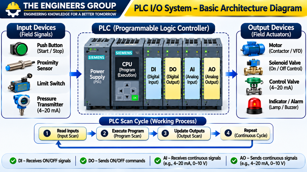
The basic signal flow of a PLC system is:
Input Devices → Input Module → PLC CPU → Output Module → Output Devices
Example:
| Input Devices | PLC Processing | Output Devices |
|---|---|---|
| Start Push Button | Control Logic | Motor Contactor |
| Stop Push Button | Interlocking | Indicator Lamp |
| Proximity Sensor | Object Detection Logic | Solenoid Valve |
| Level Transmitter | Level Control Logic | Pump or VFD |
| Pressure Transmitter | Pressure Control Logic | Control Valve |
The input module receives the field signal, and the CPU executes the programmed logic. The output module then operates the connected output device.
Important: The exact internal signal-processing sequence depends on the PLC architecture, module configuration, and I/O update method.
4. Types of PLC Input and Output
PLC I/O is broadly classified into two categories.
4.1 Digital I/O
Digital I/O handles discrete signals that represent defined states, typically ON and OFF.
Examples:
- Push Buttons
- Limit Switches
- Proximity Sensors
- Relays
- Contactors
- Solenoid Valves
Digital I/O includes:
- Digital Input (DI)
- Digital Output (DO)
4.2 Analog I/O
Analog I/O handles continuous electrical signals that represent varying process measurements or control commands.
Examples:
- Pressure Transmitters
- Temperature Transmitters
- Level Transmitters
- Flow Transmitters
- VFD Speed References
- Control Valve Position Commands
Analog I/O includes:
- Analog Input (AI)
- Analog Output (AO)
💬 NEED GUIDANCE IN PLC?
Contact THE ENGINEERS GROUP for eBook details, course information and learning support.
MESSAGE US ON WHATSAPP5. Digital Input (DI) Module
A Digital Input Module receives discrete ON/OFF signals from external field devices.
It detects the electrical status of compatible input circuits and provides the corresponding input state to the PLC.
Common Digital Input Devices
| Device | Function |
|---|---|
| Start Push Button | Gives a start command |
| Stop Push Button | Gives a stop command |
| Limit Switch | Detects mechanical position |
| Proximity Sensor | Detects nearby objects |
| Float Switch | Detects a level condition |
| Overload Auxiliary Contact | Provides overload status |
| Pressure Switch | Detects a pressure threshold |
Working Principle
Suppose a 24 V DC proximity sensor is connected to a PLC digital input.
- The sensor detects an object.
- Its output changes state.
- The digital input circuit detects the signal.
- The PLC input status changes.
- The CPU uses this status during program execution.
Common Digital Input Voltages
- 24 V DC
- 120 V AC
- 230 V AC
These are examples of available module types, not interchangeable voltage ratings. Always select a module compatible with the actual field circuit.
Example: Push Button Input
Suppose a Start Push Button is connected to PLC input I0.0.
When the operator presses the push button, the input circuit changes state. The PLC program can then use I0.0 as a start command.
6. Digital Output (DO) Module
A Digital Output Module sends discrete ON/OFF signals from the PLC to external devices.
It is used to control devices that require switching commands.
Common Digital Output Devices
| Device | Application |
|---|---|
| Contactor | Motor control |
| Relay | Electrical switching |
| Solenoid Valve | Pneumatic or hydraulic control |
| Indicator Lamp | Status indication |
| Buzzer | Audible alarm |
| Interposing Relay | Interface with external load circuits |
Types of Digital Output Modules
6.1 Relay Output
Relay output modules use mechanical contacts to switch compatible electrical loads.
Advantages:
- Can switch compatible AC and DC circuits.
- Provides contact-based switching.
- Useful for certain general-purpose control applications.
Limitations:
- Mechanical contact wear.
- Limited switching life.
- Slower switching than semiconductor outputs.
6.2 Transistor Output
Transistor output modules are commonly used for DC switching.
Advantages:
- Fast switching.
- No mechanical contacts.
- Suitable for compatible high-speed applications.
Limitations:
- Usually intended for DC loads.
- Must follow module polarity and current ratings.
6.3 Triac Output
Triac output modules are used for compatible AC switching applications.
They have specific load and leakage-current limitations, so the manufacturer’s specifications must be checked.
Important: PLC output modules are not automatically suitable for driving every motor or large electrical load directly. Use properly rated contactors, interposing relays, or other interface equipment where required.
7. Analog Input (AI) Module
An Analog Input Module receives continuous electrical signals from field instruments.
These signals represent changing process variables such as pressure, temperature, flow, and level.
Unlike digital signals, analog signals can represent many values within a defined range.
Common Analog Input Signals
- 4–20 mA
- 0–20 mA
- 0–10 V
- 1–5 V
Common Analog Input Instruments
| Instrument | Process Variable |
|---|---|
| Pressure Transmitter | Pressure |
| Temperature Transmitter | Temperature |
| Level Transmitter | Liquid Level |
| Flow Transmitter | Flow Rate |
| Load Cell Transmitter | Weight or Force |
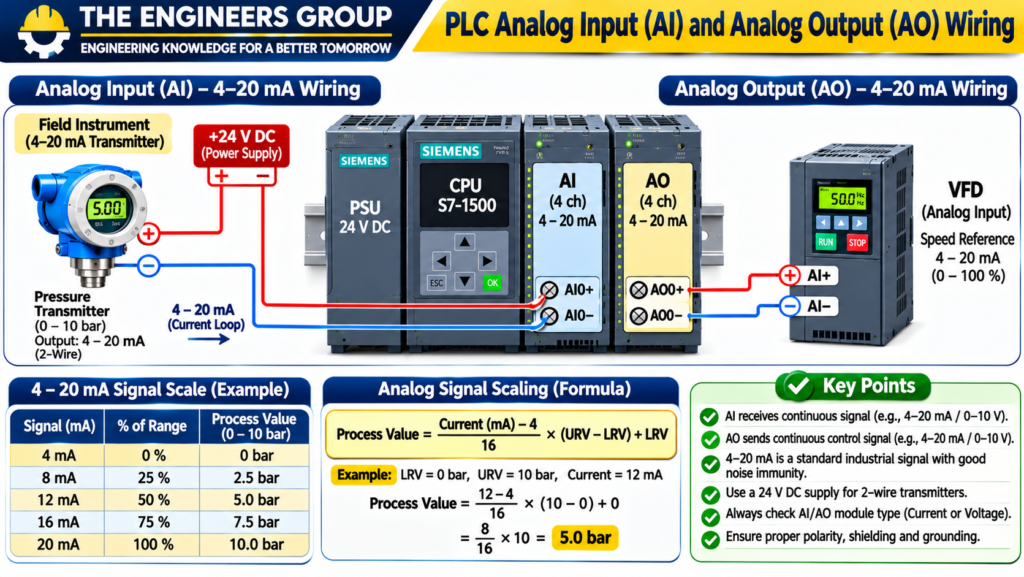
Example: 4–20 mA Pressure Measurement
Consider a pressure transmitter with the following range:
- Lower Range Value (LRV): 0 bar
- Upper Range Value (URV): 10 bar
- Output Signal: 4–20 mA
The relationship between current and pressure is:
Pressure = [(Measured Current − 4) / 16] × 10 bar
Suppose the PLC receives 12 mA.
Pressure = [(12 − 4) / 16] × 10
Pressure = 8 / 16 × 10
Pressure = 5 bar
The PLC analog input module converts the electrical signal into a digital representation that the CPU can process.
8. Analog Output (AO) Module
An Analog Output Module generates a continuous control signal from the PLC.
It is used when a device requires a variable command rather than a simple ON/OFF signal.
Common Analog Output Signals
- 4–20 mA
- 0–20 mA
- 0–10 V
Applications of Analog Output
| Device | Application |
|---|---|
| VFD | Motor speed reference |
| Control Valve Positioner | Valve position command |
| I/P Converter | Electrical-to-pneumatic conversion |
| Power Controller | Power regulation |
Example: VFD Speed Reference
Suppose a PLC analog output sends a 4–20 mA signal to a compatible VFD.
Configured reference:
- 4 mA = 0%
- 12 mA = 50%
- 20 mA = 100%
If the PLC sends 12 mA, the VFD receives a 50% speed reference according to its configured scaling.
Actual motor speed depends on the VFD settings, motor characteristics, load, and operating limits.
9. Difference Between Digital and Analog I/O
| Parameter | Digital I/O | Analog I/O |
|---|---|---|
| Signal Type | Discrete | Continuous |
| Values | ON/OFF states | Range of values |
| Common Signal | 24 V DC | 4–20 mA, 0–10 V |
| Input Example | Push Button | Pressure Transmitter |
| Output Example | Contactor | VFD Speed Reference |
| Application | Switching | Measurement and variable control |
Digital I/O is generally used for discrete control operations, while analog I/O is used for process measurement and variable control.
10. PNP and NPN Sensors
PNP and NPN are common transistor output arrangements used in industrial DC sensors.
Understanding their operation is important when connecting proximity sensors and other electronic field devices to PLC digital input modules.
10.1 PNP Sensor
A PNP sensor provides a positive voltage signal at its output when activated.
It is commonly called a sourcing output.
Typical 3-wire PNP sensor connections:
- Brown: +24 V DC
- Blue: 0 V DC
- Black: Output signal
When the sensor detects an object, its output switches toward the positive supply.
10.2 NPN Sensor
An NPN sensor switches its output toward 0 V DC when activated.
It is commonly called a sinking output.
Typical 3-wire NPN sensor connections:
- Brown: +24 V DC
- Blue: 0 V DC
- Black: Output signal
When activated, the sensor provides a path toward 0 V.
PNP vs NPN Comparison
| Parameter | PNP Sensor | NPN Sensor |
|---|---|---|
| Output Action | Switches toward +V | Switches toward 0 V |
| Common Description | Sourcing | Sinking |
| Active Output | Positive voltage | Near 0 V |
| Connection | Compatible sourcing/receiving input arrangement | Compatible sinking/receiving input arrangement |
Important: Confirm the PLC input module’s common terminal arrangement and the sensor wiring diagram before connecting a PNP or NPN sensor. Do not assume every PLC input module supports both arrangements.
11. Sinking and Sourcing Concepts
Sinking and sourcing describe how current flows through a DC control circuit.
These concepts are important when connecting PLC input modules, output modules, and field sensors.
Sourcing
A sourcing device supplies current from the positive supply side to the connected circuit.
For example, a PNP sensor typically sources current to a compatible PLC input circuit.
Sinking
A sinking device provides a path for current to return toward 0 V.
For example, an NPN sensor typically sinks current from a compatible input circuit.
Simple Comparison
| Term | Meaning |
|---|---|
| Sourcing | Supplies current from positive supply |
| Sinking | Provides current return path toward 0 V |
| PNP | Commonly associated with sourcing output |
| NPN | Commonly associated with sinking output |
The correct arrangement depends on the PLC module design and the field device.
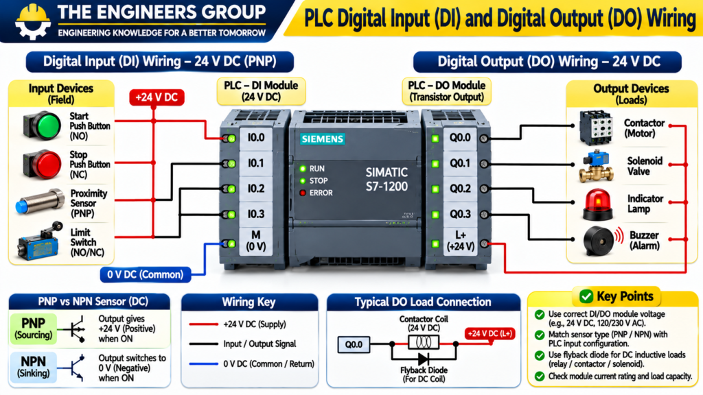
12. PLC Digital Input Wiring
Digital input wiring connects field switches and sensors to the PLC input module.
Common devices include:
- Push Buttons
- Limit Switches
- Proximity Sensors
- Float Switches
- Auxiliary Relay Contacts
Example: 24 V DC PNP Sensor
Typical connections:
- Brown wire → +24 V DC
- Blue wire → 0 V DC
- Black wire → Compatible PLC digital input
- PLC input common → Appropriate 0 V reference according to module wiring design
When the sensor detects an object, the black output wire provides a positive signal to the compatible PLC input.
Digital Input Wiring Checks
- Verify sensor supply voltage.
- Check the sensor output type.
- Confirm PLC input module compatibility.
- Check terminal connections.
- Observe the input status LED.
- Verify the input address in the PLC program.
13. PLC Digital Output Wiring
Digital output wiring connects the PLC output module to external control devices.
Common loads include:
- Relays
- Contactors
- Solenoid Valves
- Indicator Lamps
- Buzzers
Example: PLC Output to Contactor Coil
Suppose a PLC transistor or relay output operates a compatible 24 V DC contactor coil.
Basic operation:
- The CPU executes the control logic.
- The PLC output turns ON.
- The output circuit energizes the contactor coil.
- The contactor changes its contact state.
- The connected motor power circuit operates through the contactor’s properly rated main contacts.
The output module must be compatible with the coil voltage, current, polarity, and switching characteristics.
For inductive loads, use appropriate suppression components as recommended by the equipment manufacturer.
14. PLC Analog Input Wiring
Analog input wiring connects field transmitters to PLC analog input modules.
Common signals include 4–20 mA and 0–10 V.
Example: Two-Wire 4–20 mA Transmitter
A typical loop includes:
- DC power supply
- Two-wire transmitter
- PLC analog current input
- Appropriate loop wiring
The transmitter controls the loop current according to the measured process variable.
For a typical 4–20 mA loop:
- 4 mA represents 0% of configured range.
- 12 mA represents 50% of configured range.
- 20 mA represents 100% of configured range.
Analog Wiring Precautions
- Confirm whether the AI module is active or passive.
- Check the transmitter power requirements.
- Verify current or voltage input configuration.
- Follow the correct polarity.
- Use suitable shielded cable where required.
- Separate analog wiring from noisy power wiring.
- Apply grounding and shield termination according to the manufacturer’s guidelines.
15. PLC Analog Output Wiring
Analog output wiring connects PLC AO channels to external devices.
Common applications include VFD reference signals and control valve positioners.
Example: PLC AO to VFD
Suppose the PLC sends a 4–20 mA signal to a VFD analog input.
Typical configuration:
- PLC AO positive → VFD analog input positive
- PLC AO return → VFD analog common
The exact wiring depends on whether the analog output is active or passive and the VFD input design.
Analog Output Precautions
- Check output signal type.
- Confirm the VFD input configuration.
- Verify current and voltage ratings.
- Check signal scaling.
- Verify common and return connections.
- Follow grounding and shielding recommendations.
16. PLC I/O Addressing
PLC I/O Addressing identifies individual input and output points in a PLC program.
It allows the programmer to reference the correct physical or configured I/O channel.
Different PLC manufacturers use different addressing systems.
Example: Siemens-Style Addressing
A simplified example:
| Address | Description |
|---|---|
| I0.0 | Digital Input Bit 0 |
| I0.1 | Digital Input Bit 1 |
| I0.2 | Digital Input Bit 2 |
| Q0.0 | Digital Output Bit 0 |
| Q0.1 | Digital Output Bit 1 |
| Q0.2 | Digital Output Bit 2 |
In this notation:
- I represents input.
- Q represents output.
- The byte number identifies the address group.
- The bit number identifies an individual digital point.
For analog I/O, PLC platforms may use input and output words or configured tags. For example, IW64 may represent an input word and QW64 may represent an output word in certain Siemens addressing configurations.
Important: Actual addresses depend on hardware configuration, module slot, assigned start addresses, and PLC family. Always check the project hardware configuration.
17. Practical Industrial PLC I/O Example
Let’s understand a practical application using a tank level control system.
Application: Automatic Water Tank Filling
Required Input Devices
| Device | PLC Signal | Function |
|---|---|---|
| Start Push Button | Digital Input | Starts automatic operation |
| Stop Push Button | Digital Input | Stops operation |
| Level Transmitter | Analog Input | Measures tank level |
| Low-Level Alarm Contact | Digital Input | Provides low-level status, if used |
Required Output Devices
| Device | PLC Signal | Function |
|---|---|---|
| Pump Contactor | Digital Output | Starts or stops pump |
| High-Level Alarm | Digital Output | Indicates high level |
| VFD Speed Reference | Analog Output | Controls pump speed, if required |
Working Principle
- The level transmitter continuously measures the tank level.
- The analog input module receives the transmitter signal.
- The PLC scales the signal into an engineering value.
- The CPU compares the measured level with the configured setpoints.
- When the level reaches the low threshold, the PLC can start the pump if all permissives are healthy.
- When the level reaches the high threshold, the PLC stops the pump.
- The HMI can display the tank level and pump status.
For example:
- Low-level start threshold: 30%
- High-level stop threshold: 90%
These are illustrative setpoints. Actual values depend on the process design.
18. Common PLC I/O Problems and Troubleshooting
PLC I/O faults can cause machine stoppages and incorrect process operation.
The following table lists common issues and their basic checks.
| Problem | Possible Cause | Basic Troubleshooting |
|---|---|---|
| Digital Input Not Turning ON | Sensor or wiring fault | Check supply, output signal and input LED |
| Digital Output Not Working | Output fault or load issue | Check PLC logic, output LED and load circuit |
| Analog Input Reading Zero | Open loop or incorrect wiring | Check transmitter supply and loop current |
| Analog Reading Incorrect | Scaling or configuration error | Verify range and engineering scaling |
| Analog Output Not Changing | Incorrect configuration | Check program value and AO configuration |
| Sensor Not Detected | Wrong sensor type or alignment | Check sensor type, distance and wiring |
| Communication I/O Fault | Network or configuration problem | Check diagnostics and network status |
| Output Fuse Blown | Short circuit or overload | Isolate load and inspect wiring |
Important Troubleshooting Procedure
- Check the PLC module status LEDs.
- Check field device power supply.
- Verify wiring and terminal connections.
- Check the actual input or output status online.
- Verify program logic and interlocks.
- Check analog scaling and channel configuration.
- Review PLC diagnostics and fault messages.
- Consult the manufacturer’s hardware manual.
Safety Note: Follow lockout/tagout procedures and verify absence of hazardous voltage before working on electrical wiring. Do not disconnect live circuits unless the equipment and approved procedure specifically permit it.
19. Important PLC I/O Terminology
| Term | Meaning |
|---|---|
| DI | Digital Input |
| DO | Digital Output |
| AI | Analog Input |
| AO | Analog Output |
| I/O | Input/Output |
| PNP | Positive switching transistor output arrangement |
| NPN | Negative switching transistor output arrangement |
| LRV | Lower Range Value |
| URV | Upper Range Value |
| HMI | Human Machine Interface |
| VFD | Variable Frequency Drive |
| 4–20 mA | Industrial analog current signal |
| 0–10 V | Analog voltage signal |
| Scaling | Converting raw values into engineering units |
| Channel | Individual input or output point |
FREE 100 PLC INTERVIEW Q&A PDF DOWNLOAD
Download your free PLC learning material.
📥 DOWNLOAD FREE PLC PDFTHE ENGINEERS GROUP
20. PLC I/O Interview Questions and Answers
Q1. What is PLC I/O?
PLC I/O is the interface that connects a PLC with external input and output devices.
Q2. What is a Digital Input Module?
It receives discrete ON/OFF signals from field devices such as switches and sensors.
Q3. What is a Digital Output Module?
It sends discrete control signals to devices such as relays, contactors, and solenoid valves.
Q4. What is an Analog Input Module?
It receives continuous signals such as 4–20 mA and 0–10 V from field instruments.
Q5. What is an Analog Output Module?
It generates continuous signals to control devices such as VFDs and control valve positioners.
Q6. What is the difference between DI and AI?
DI receives discrete signals, while AI receives continuous analog signals.
Q7. What is the difference between DO and AO?
DO sends ON/OFF signals, while AO generates variable analog signals.
Q8. What is a PNP Sensor?
A PNP sensor provides a positive voltage signal at its output when activated.
Q9. What is an NPN Sensor?
An NPN sensor switches its output toward 0 V when activated.
Q10. What is sourcing?
Sourcing means supplying current from the positive supply side to a circuit.
Q11. What is sinking?
Sinking means providing a current return path toward 0 V.
Q12. What is a 4–20 mA Signal?
It is a common industrial analog current signal used to transmit process measurements.
Q13. Why is 4–20 mA commonly used?
It offers good noise immunity for industrial transmission and allows 4 mA to represent a live zero in many applications.
Q14. What is a PLC Digital Output used for?
It is used to switch compatible devices such as relays, contactors, lamps, and solenoid valves.
Q15. What is the function of an Analog Input Module?
It receives analog electrical signals and converts them into digital values for PLC processing.
Q16. What is PLC I/O Addressing?
It is the method used to identify individual input and output points in a PLC program.
Q17. What does I0.0 represent in Siemens-style addressing?
It represents input byte 0, bit 0 in the applicable addressing configuration.
Q18. What does Q0.0 represent in Siemens-style addressing?
It represents output byte 0, bit 0 in the applicable addressing configuration.
Q19. What should you check if an analog input reads zero?
Check transmitter power, loop wiring, polarity, module configuration, and measured loop current.
Q20. What is signal scaling in PLC?
Signal scaling converts raw analog input or output values into the required engineering range.
21. PLC I/O MCQs
Q1. What does DI stand for?
A. Digital Indicator
B. Digital Input
C. Data Interface
D. Direct Input
Correct Answer: B. Digital Input
Q2. Which signal is commonly received by an Analog Input Module?
A. ON/OFF
B. 4–20 mA
C. Relay Contact Only
D. Push Button Contact
Correct Answer: B. 4–20 mA
Q3. Which device is commonly connected to a Digital Input Module?
A. Pressure Transmitter
B. Temperature Transmitter
C. Push Button
D. VFD Speed Reference
Correct Answer: C. Push Button
Q4. Which PLC output is used for variable motor speed reference?
A. Digital Input
B. Digital Output
C. Analog Output
D. Digital Sensor
Correct Answer: C. Analog Output
Q5. What does a PNP sensor provide when activated?
A. Positive voltage signal
B. Negative voltage signal only
C. AC voltage
D. No signal
Correct Answer: A. Positive voltage signal
Q6. What does an NPN sensor typically switch toward?
A. +24 V
B. 0 V
C. 230 V AC
D. 110 V AC
Correct Answer: B. 0 V
Q7. Which device is commonly operated through a Digital Output?
A. Pressure Transmitter
B. Contactor
C. Temperature Sensor
D. Flow Transmitter
Correct Answer: B. Contactor
Q8. What does AO stand for?
A. Automatic Operation
B. Analog Output
C. Active Output
D. Analog Operation
Correct Answer: B. Analog Output
Q9. Which signal represents a common industrial current loop?
A. 1–10 V
B. 4–20 mA
C. 0–5 A
D. 230 V AC
Correct Answer: B. 4–20 mA
Q10. What does I represent in Siemens-style PLC addressing?
A. Internal Relay
B. Input
C. Indicator
D. Interface
Correct Answer: B. Input
Q11. What does Q represent in Siemens-style PLC addressing?
A. Input
B. Output
C. Counter
D. Timer
Correct Answer: B. Output
Q12. Which module receives signals from a pressure transmitter?
A. Digital Output
B. Analog Input
C. Digital Input
D. Analog Output
Correct Answer: B. Analog Input
Q13. Which module sends a variable control signal to a control valve positioner?
A. Digital Input
B. Digital Output
C. Analog Output
D. Power Supply
Correct Answer: C. Analog Output
Q14. What is the purpose of signal scaling?
A. Increase supply voltage
B. Convert raw values into engineering units
C. Change PLC hardware
D. Reset the CPU
Correct Answer: B. Convert raw values into engineering units
Q15. Which device detects an object without physical contact?
A. Proximity Sensor
B. Contactor
C. Fuse
D. Push Button
Correct Answer: A. Proximity Sensor
22. Chapter Summary
In this chapter, we learned about the PLC Input and Output (I/O) System and its importance in industrial automation.
We covered Digital Input, Digital Output, Analog Input, and Analog Output modules. We also studied PNP and NPN sensors, sinking and sourcing concepts, PLC I/O wiring, addressing, signal scaling, and practical industrial applications.
We explored how PLCs receive signals from field devices, process the information, and control external equipment.
Understanding PLC I/O is essential for PLC programming, panel wiring, commissioning, maintenance, and troubleshooting.
23. What You Will Learn in Chapter 05
In the next chapter, we will study:
PLC Programming Languages – Ladder Logic, Function Block Diagram, Structured Text and IEC 61131-3
Topics will include:
- Introduction to PLC Programming Languages
- Ladder Logic (LD)
- Function Block Diagram (FBD)
- Structured Text (ST)
- Sequential Function Chart (SFC)
- Instruction List (IL) – Historical IEC language
- IEC 61131-3 Overview
- Practical Ladder Logic Examples
- PLC Programming Best Practices
- Interview Questions and MCQs
Continue learning with THE ENGINEERS GROUP.
THE ENGINEERS GROUP
ENGINEERING KNOWLEDGE FOR A BETTER TOMORROW
Learn. Practice. Grow.
CONNECT WITH THE ENGINEERS GROUP
Learn. Practice. Improve. Grow.
📘 EXPLORE OUR EBOOK 💬 CONTACT US ON WHATSAPP ▶️ SUBSCRIBE ON YOUTUBE FOLLOW US ON FACEBOOKTHE ENGINEERS GROUP
Free Engineering Education for Everyone